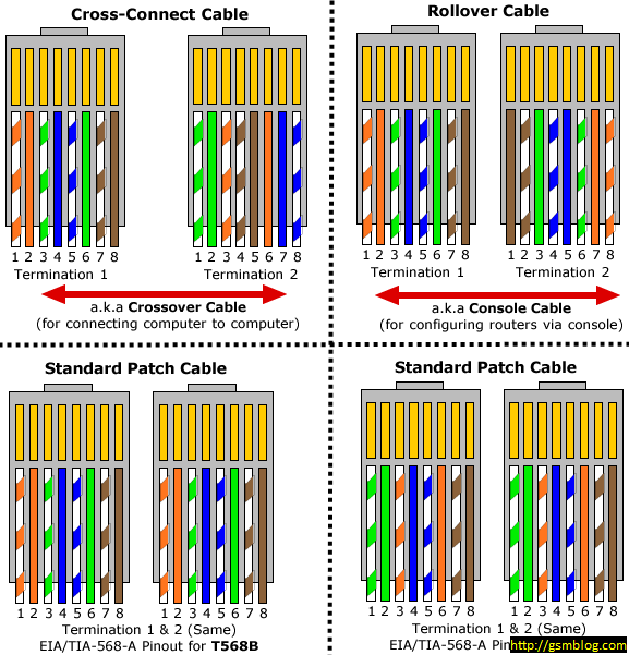
Rj45 A Pattern
Rj45 A Pattern - Explaining 568a, 568b, ethernet pin connectors, and crossover cables. It’s similar to a telephone jack, but it is wider. 244 views 4 weeks ago. Luxury textiles , leather , wallpaper , rugs , pillows , and throws. Molded fiber enclosure is 617 cid. Web one key difference between the a and b wiring standards is the pin assignments for the individual wires within the connector. A pinout is a specific arrangement of wires that dictate how the connector is terminated. Feel free to print it and carry it with you. If you want a larger diagram see further below. Both these standards have the same number and color of wires. Web the choice between t568a and t568b depends on your specific application scenario, backward compatibility needs, consistency, and manufacturer preferences. Both schemes are perfectly normal to use providing they are not mixed. Web one key difference between the a and b wiring standards is the pin assignments for the individual wires within the connector. Web rj45 cable pinout with color. The connector of ethernet cable has two standards, i.e., t568a and t568b. Web the choice between t568a and t568b depends on your specific application scenario, backward compatibility needs, consistency, and manufacturer preferences. Power over ethernet (poe) and rj45. Most connectors are described through their prongs that attach to port; If you have a crimping tool, strip away a portion of. Wiring scheme a (or t568a) used for rj45 wiring, uses different wiring colours to scheme b (or t568b). It’s similar to a telephone jack, but it is wider. Web the rj45 connector pinout diagram consists of eight pins, each serving a specific purpose. Rj45 pinout wiring diagram (std t568b). Applicable standards of the rj45 connector. Are any of these terms being misused? If you’ve been around the networking world for even a short duration, you’ve heard lots of terms that are thrown around referring to cabling. Both follow a convention of coating individual wires in one of five colors (brown, green, orange, blue, or white) with certain stripe and solid combinations. Rj45 technical specifics/board layout. Let’s discuss t568a and t568b pinout standards in detail. Normally a string of colors is difficult to remember similarly to phone numbers. Web rj45 wiring diagram t568a standard. Visit the fluke networks website to learn more. These pins are responsible for transmitting and receiving data, as well as providing power to devices that require it. I teach you both a and b pattern in this video. Rj45 technical specifics/board layout considerations. Wiring scheme a is the default scheme in. Web vigilant vlp comms box specifications. Power over ethernet (poe) and rj45. Web (a and b pattern) jc pierce. Interior design showroom to the trade. Web one key difference between the a and b wiring standards is the pin assignments for the individual wires within the connector. If you have a crimping tool, strip away a portion of the sheath, untangle and arrange the wires in the. If you want a larger. Both these standards have the same number and color of wires. Most connectors are described through their prongs that attach to port; The t568a and t568b standards. These pins are responsible for transmitting and receiving data, as well as providing power to devices that require it. Web one key difference between the a and b wiring standards is the pin. Web one key difference between the a and b wiring standards is the pin assignments for the individual wires within the connector. These pins are responsible for transmitting and receiving data, as well as providing power to devices that require it. Current uses of rj45 devices. Rj45 technical specifics/board layout considerations. Web rj45 wiring diagram t568a standard. Web the choice between t568a and t568b depends on your specific application scenario, backward compatibility needs, consistency, and manufacturer preferences. A quick video on how to put in an rj45 connector. Both follow a convention of coating individual wires in one of five colors (brown, green, orange, blue, or white) with certain stripe and solid combinations. A rj45 connector is. Most connectors are described through their prongs that attach to port; Both follow a convention of coating individual wires in one of five colors (brown, green, orange, blue, or white) with certain stripe and solid combinations. To properly wire an rj45 cat 5 cable, it is important to understand the pinout diagram. Web rj45 wiring diagram t568a standard. Web one key difference between the a and b wiring standards is the pin assignments for the individual wires within the connector. Web the choice between t568a and t568b depends on your specific application scenario, backward compatibility needs, consistency, and manufacturer preferences. Both these standards have the same number and color of wires. Magnet, 8 ohm impedance, and an rj45 input. Web here is a simple rj45 pinout diagram (which still shows the wiring you need): Waveform, false color, focus assist; It’s similar to a telephone jack, but it is wider. Wiring scheme a is the default scheme in. The only difference lies in the positions of green and orange wires. Explaining 568a, 568b, ethernet pin connectors, and crossover cables. It uses all eight pins for transmission and reception of data signals, along with dedicated pins for power over ethernet (poe) applications. Wiring scheme a (or t568a) used for rj45 wiring, uses different wiring colours to scheme b (or t568b).
rj45 cable color code Wiring Diagram and Schematics
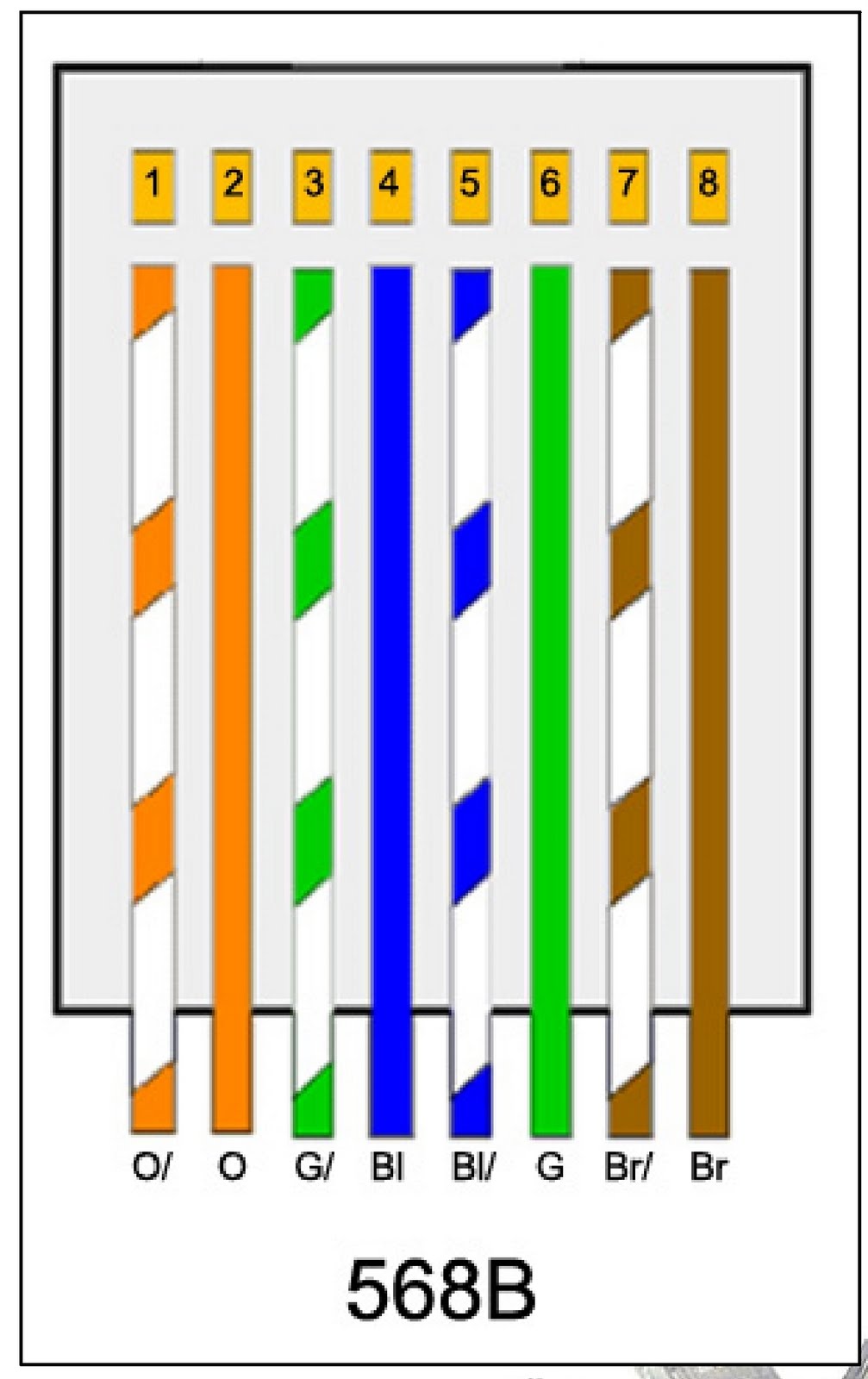
Rj45 Connector 568a Wiring Diagram
Rj45 Pins Layout PCB Designs
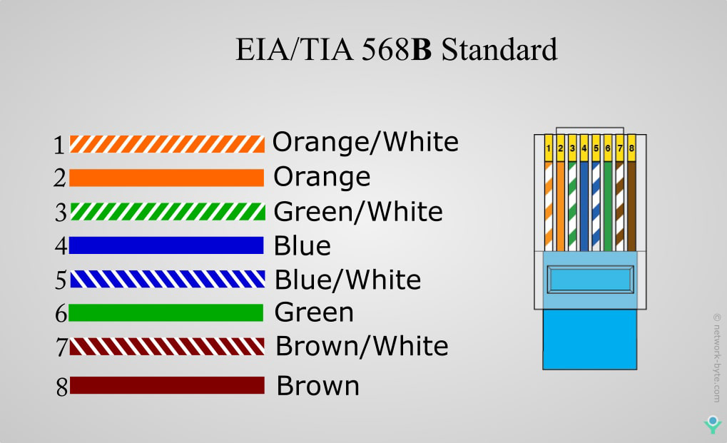
Cable Color Code Rj45
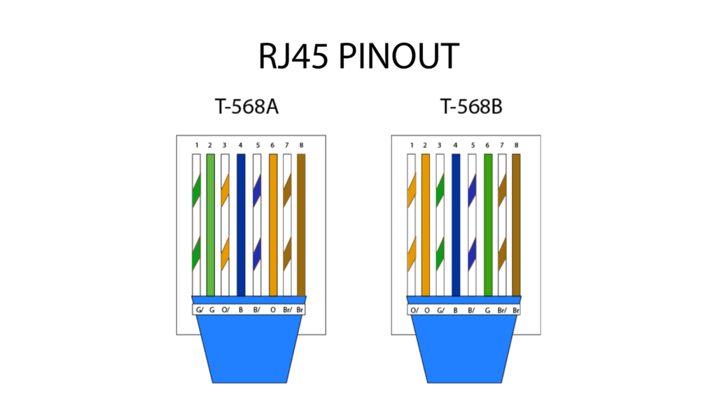
Rj45 Pinout 568b
RJ45 Pinout Diagram, Colour Code, Wiring Diagram(cat 6,7,5e) ETechnoG
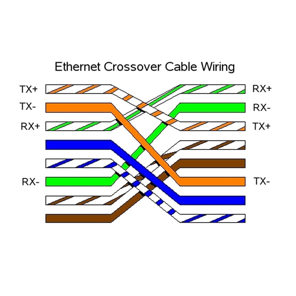
Network Crossover Cable Wiring Diagram Rj45 Pinout Images
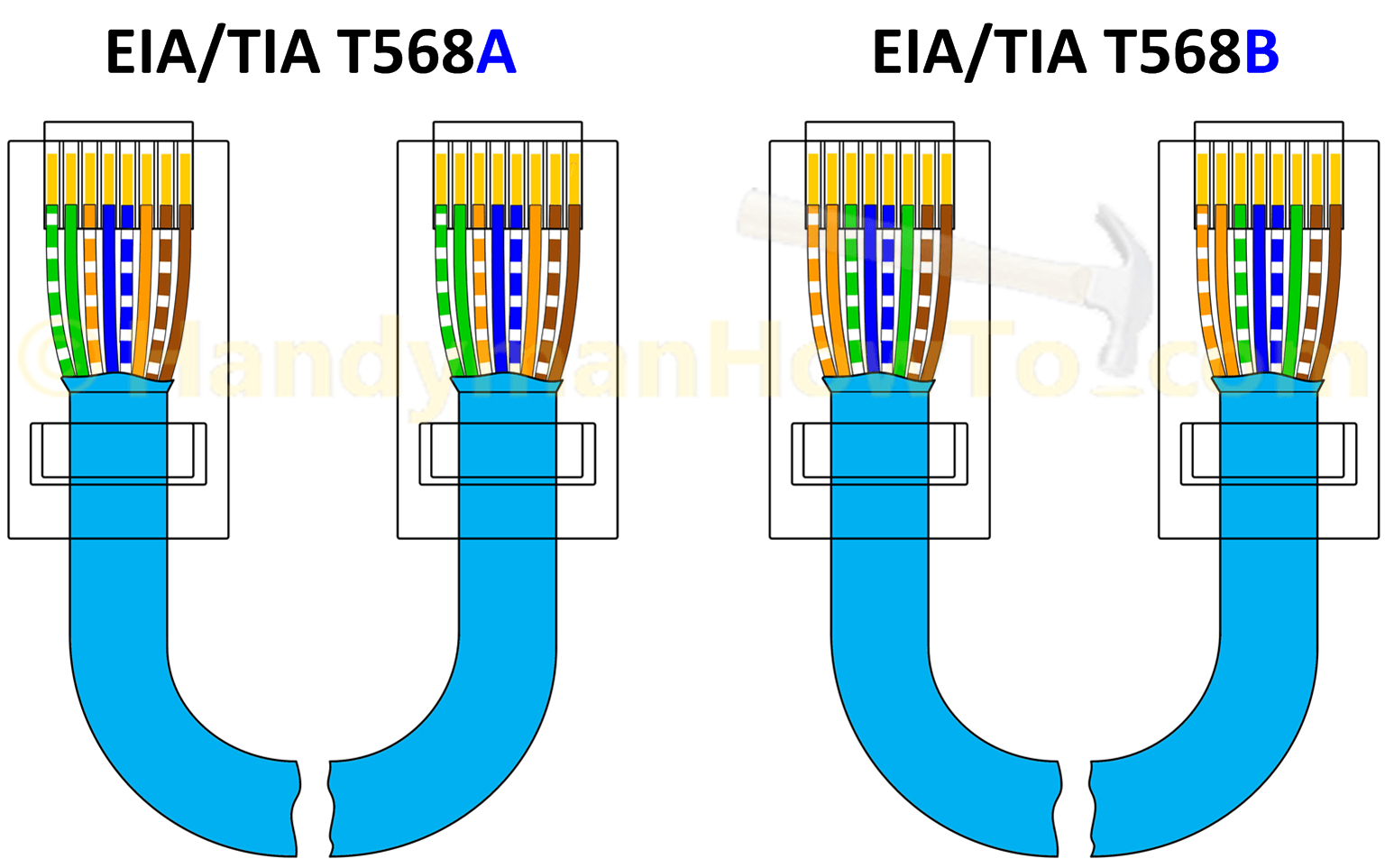
Rj45 Wiring Diagram Standard

RJ45 crossover pin assignment in T568A and T568B connections types

RJ45 Cable Tester Expert Circuits
The T568A And T568B Standards.
Rj45 Technical Specifics/Board Layout Considerations.
Web The Rj45 Connector Pinout Diagram Consists Of Eight Pins, Each Serving A Specific Purpose.
If You Have A Crimping Tool, Strip Away A Portion Of The Sheath, Untangle And Arrange The Wires In The.
Related Post:
