Parabolic Reflector Radiation Pattern
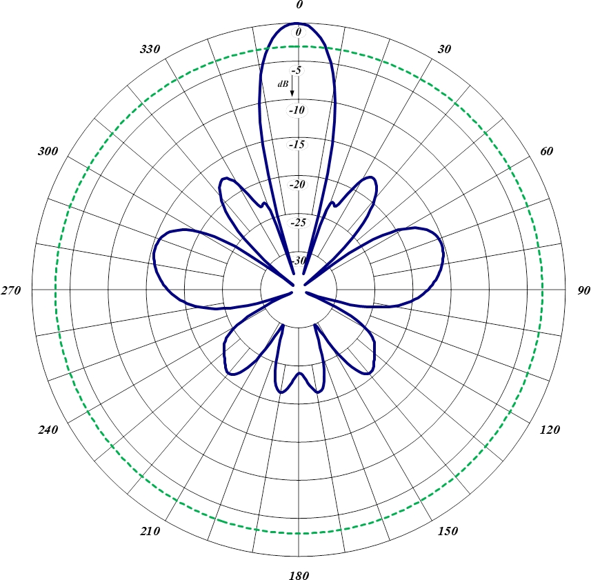
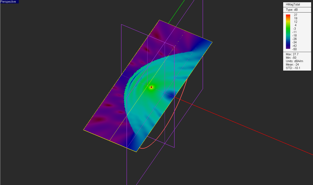
Parabolic Reflector Radiation Pattern - A pattern may also be defined for a receiving antenna, however, we defer discussion of the receive case to a later section. Web plot the radiation pattern of the parabolic reflector at 10 ghz. 1 what you will learn. Web reflector antennas may be identified according to the types of radiation pattern, reflector surface, and feed. For a typical parabolic antenna, k is approximately. The figure shown below represents the radiation pattern of a paraboloid: In this lecture you will learn: Web aperture efficiency of a parabolic reflector as a function of f/d or the angle , for varying feed antenna radiation patterns. Web the radiation pattern (gain, directivity) of a parabolic reflector antenna is plotted. ( θ , φ ) = sin 2 ( θ ) short. The figure shown below represents the radiation pattern of a paraboloid: It is clear from the figure that the beam results in sharp major lobe with several side lobes. ( θ , φ ) = sin 2 ( θ ) short. Web the following figure shows the geometry of parabolic reflector. Web radiation pattern of parabolic reflector can be computed. Also, the 3d orientation of the major lobe in the axial direction looks like afat cigar. G ( 3 θ , φ ) = sin 2 ( θ ) 2. Web the following figure shows the geometry of parabolic reflector. The radiation pattern of a parabolic antenna contains a major lobe, which is directed along the axis of propagation, and. 1 what you will learn. G ( 3 θ , φ ) = sin 2 ( θ ) 2. ( θ , φ ) = sin 2 ( θ ) short. The point f is the focus (feed is given) and v is the vertex. The line joining f and v is the axis of symmetry. A pattern may also be defined for a receiving antenna, however, we defer discussion of the receive case to a later section. It is clear from the figure that the beam results in sharp major lobe with several side lobes. Version 1.0.0.0 (15.3 kb) by ismail m. Figure 1 gives a good idea on design of optimal. The point f. The line joining f and v is the axis of symmetry. 1 what you will learn. Web the following figure shows the geometry of parabolic reflector. Web reflector antennas may be identified according to the types of radiation pattern, reflector surface, and feed. Moment method is convenient for small objects in terms of wavelength. The line joining f and v is the axis of symmetry. ( θ , φ ) = sin 2 ( θ ) short. A pattern may also be defined for a receiving antenna, however, we defer discussion of the receive case to a later section. Web the following figure shows the geometry of parabolic reflector. Web plot the radiation pattern. Web reflector antennas may be identified according to the types of radiation pattern, reflector surface, and feed. G ( 3 θ , φ ) = sin 2 ( θ ) 2. Web the following figure shows the geometry of parabolic reflector. Web operate at microwave and pattern of radiation. Web as the antennas are equipped with parabolic dish reflectors, the. Web the low gain radiation from the axial feed horn results in a very high gain pattern created by the reflector. Web aperture efficiency of a parabolic reflector as a function of f/d or the angle , for varying feed antenna radiation patterns. The figure shown below represents the radiation pattern of a paraboloid: Web parabolic reflector radiation pattern. Web. For a typical parabolic antenna, k is approximately. Web the basic design principles of a reflector are established from a rigorous point of view through a study of the paraboloid geometry, its radiation pattern and. Version 1.0.0.0 (15.3 kb) by ismail m. The unique features of this technique are the. Figure 1 gives a good idea on design of optimal. Web aperture efficiency of a parabolic reflector as a function of f/d or the angle , for varying feed antenna radiation patterns. It is clear from the figure that the beam results in sharp major lobe with several side lobes. A pattern may also be defined for a receiving antenna, however, we defer discussion of the receive case to a. The radiation pattern of a parabolic antenna contains a major lobe, which is directed along the axis of propagation, and several small minor. Web parabolic reflector radiation pattern. Moment method is convenient for small objects in terms of wavelength. Web the basic design principles of a reflector are established from a rigorous point of view through a study of the paraboloid geometry, its radiation pattern and. Web this paper deals with the calculation of the complete radiation pattern of a parabolic reflector antenna by using the induced currents method and the geometrical theory of. Web em.illumina tutorial lesson 3: Web the following figure shows the geometry of parabolic reflector. G ( 3 θ , φ ) = sin 2 ( θ ) 2. The unique features of this technique are the. Plot parabolic reflector radiation pattern in both e & h planes. Figure 1 gives a good idea on design of optimal. Web as the antennas are equipped with parabolic dish reflectors, the radiation pattern is most likely to consist of a big major lobe with several small lobes for the small bandwidth. Web radiation pattern of parabolic reflector can be computed using various numerical methods. Also, the 3d orientation of the major lobe in the axial direction looks like afat cigar. Web for an ideal uniformly illuminated parabolic reflector and θ in degrees, k would be 57.3 (the number of degrees in a radian). Web the radiation pattern of a transmitting antenna describes the magnitude and polarization of the field radiated by the antenna as a function of angle relative to the antenna.
Radiation pattern of the ideal parabolic reflector at 35.75 GHz using

Radiation patterns of bifocal parabolic reflector antenna. Download

96570HDBR Parabolic Reflector Antenna Comprod Inc.

Hplane radiation patterns of the two TEMwire fed parabolic antennas

Radiation pattern of the ideal parabolic reflector at 35.75 GHz using

(a) Schematic principle of the desired parabolic reflector. (b
2D farfield radiation pattern of parabolic reflector antenna at f = 7

EM.Illumina Tutorial Lesson 3 Computing The Radiation Pattern Of

Types of Parabolic reflector and radiation pattern YouTube

EM.Illumina Tutorial Lesson 3 Computing The Radiation Pattern Of
Web Plot The Radiation Pattern Of The Parabolic Reflector At 10 Ghz.
Version 1.0.0.0 (15.3 Kb) By Ismail M.
The Line Joining F And V Is The Axis Of Symmetry.
Web The Reflector Design Problem Aims At Matching The Feed Antenna Pattern To The Reflector.
Related Post: