Loop Antenna Radiation Pattern
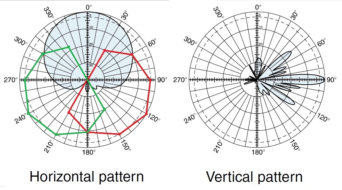
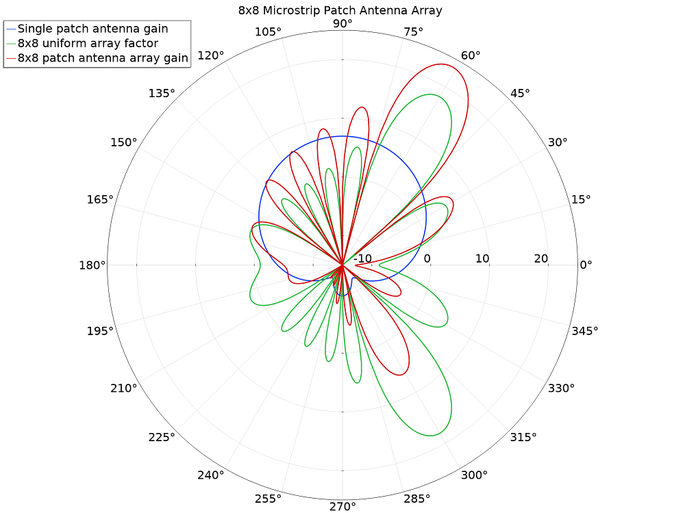
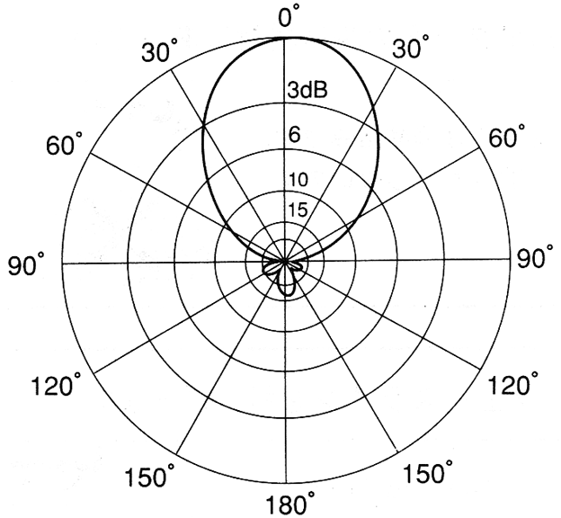
Loop Antenna Radiation Pattern - A pattern may also be defined for a receiving antenna, however, we defer discussion of the receive case to a later section. Web a half wave antenna fits one positive or negative part of the wave. Web azimuth radiation pattern of a horizontally polarized full wave loop antenna in free space. To have a better understanding, consider the following figure, which represents the radiation pattern of a dipole antenna. Half wave dipole antenna (l=0.5 λ) current distribution. Loop antennas come in various sizes and shapes, with very different characteristics. Dipole antenna (l = λ) wavelength= 3.3 cm. Equivalent circuit of the loop antenna. Dipole antenna (l = 2λ) magnitude/ amplitude. Ferrite loops.) introduction loop antennas form another antenna type, which features simplicity, low cost and versatility. A novel reconfiguration scheme is adopted that only switches the phase of the electric dipole by 180° in an electrically small huygens (complementary) source. The radiation patterns for different angles of looping are also illustrated clearly in the figure. Last updated 28 november 2023. These antennas have low radiation resistance and high inductive reactance, so that their impedance is difficult. Web the radiation pattern of a transmitting antenna describes the magnitude and polarization of the field radiated by the antenna as a function of angle relative to the antenna. These antennas have low radiation resistance and high inductive reactance, so that their impedance is difficult to match to a radio impedance (often 50 ohms). Web the antenna feed points would. By the time the loop That makes the radiation pattern weird. Web full wave loops, (generally between 2/3 and 3/2 wavelengths) which have maximum radiation broadside to the loop. In the representation of radiation pattern, we often come across different shapes, which indicate the major and minor radiation areas, by which the radiation efficiency of the antenna is known. Web. By the time the loop Web loop antennas are usually classified as electrically small ( c < λ / 3 ) and electrically large (c ∼ λ ). Last updated 28 november 2023. In the second part of this antenna basics series, you will learn more about the physics of how antennas work. While 1 wavelength loops radiate broadside to. Equivalent circuit of the loop antenna. Loop antennas (radiation parameters of a small loop. Ferrite loops.) introduction loop antennas form another antenna type, which features simplicity, low cost and versatility. Last updated 28 november 2023. The pattern is similar to a dipole, but about 6 degrees wider however, the vertical pattern is more compressed, providing about 1 db of gain. Equivalent circuit of the loop antenna. Larger loops, 2 wavelengths or more, which have maximum radiation off the sides of the loop, and may have a broadside null. Ferrite loops.) introduction loop antennas form another antenna type, which features simplicity, low cost and versatility. The radiation patterns for different angles of looping are also illustrated clearly in the figure. This. The radiation patterns for different angles of looping are also illustrated clearly in the figure. Your requirements may be different, but the analysis process that lead up to it may still be of. Half wave dipole antenna (l=0.5 λ) current distribution. 80m horizontal loop for field day. These antennas have low radiation resistance and high inductive reactance, so that their. Antennas allow information to be transferred to distant locations. In the second part of this antenna basics series, you will learn more about the physics of how antennas work. Dipole antenna (l = 2λ) magnitude/ amplitude. To have a better understanding, consider the following figure, which represents the radiation pattern of a dipole antenna. This chapter on loop antennas covers. A novel reconfiguration scheme is adopted that only switches the phase of the electric dipole by 180° in an electrically small huygens (complementary) source. This chapter on loop antennas covers implementation aspects of both electrically small and electrically large loops which have a wide range of applications. This null progressively fills in as one makes the loop diameter larger. That. Courtesy himanshu rohilla, 3rd year ee, iit delhi. As the frequency progresses to the second and third resonances the perpendicular radiation fades and strong lobes near the plane of the loop arise. October 12, 2016 by mark hughes. Web an antenna is a device that couples currents to electromagnetic waves for purposes of radiation or reception. Last updated 2 december. The small loop as a receiving antenna. As we did with loop antenna theory, we will them into the following types: To have a better understanding, consider the following figure, which represents the radiation pattern of a dipole antenna. 80m horizontal loop for field day. A quarter wave antenna is the same as a half wave but the other half (quarter wave) part of the antenna is a ground plane or the surroundings. Your requirements may be different, but the analysis process that lead up to it may still be of. Web the radiation pattern of a transmitting antenna describes the magnitude and polarization of the field radiated by the antenna as a function of angle relative to the antenna. By the time the loop Equivalent circuit of the loop antenna. Dipole antenna (l = 2λ) magnitude/ amplitude. Web theory of large loop antennas. This null progressively fills in as one makes the loop diameter larger. A novel reconfiguration scheme is adopted that only switches the phase of the electric dipole by 180° in an electrically small huygens (complementary) source. Web a radiation pattern defines the variation of the power radiated by an antenna as a function of the direction away from the antenna. Dipole antenna (l = λ) wavelength= 3.3 cm. Half wave dipole antenna (l=0.5 λ) current distribution.
Simulated radiation patterns of the reference rectangular loop antenna

Omnidirectional Antenna Radiation Patterns Explained MP Antenna

Antenna Radiation Pattern and Antenna Tilt RAYmaps

Radiation pattern plot of the loop antenna. Download

How to Synthesize the Radiation Pattern of an Antenna Array COMSOL Blog

Loop Antenna Radiation Pattern

Omnidirectional Antenna Radiation Pattern

Omnidirectional Antenna Radiation Pattern

RadiationPatternLoopAntenna IoT M2M blog

14 Radiation Pattern of Small and Large Loop Antenna Download
Web The Antenna Feed Points Would Be In Series With The Loop, Such That A Small Loop Looks Somewhat Like A Short Circuit Across The Antenna Feed.
This Still Qualifies As A “Small Loop”, But Is Beginning To Show Some Of The Characteristics Of A Larger Loop.
A Pattern May Also Be Defined For A Receiving Antenna, However, We Defer Discussion Of The Receive Case To A Later Section.
Web Full Wave Loops, (Generally Between 2/3 And 3/2 Wavelengths) Which Have Maximum Radiation Broadside To The Loop.
Related Post: