Technical Drawing Meaning
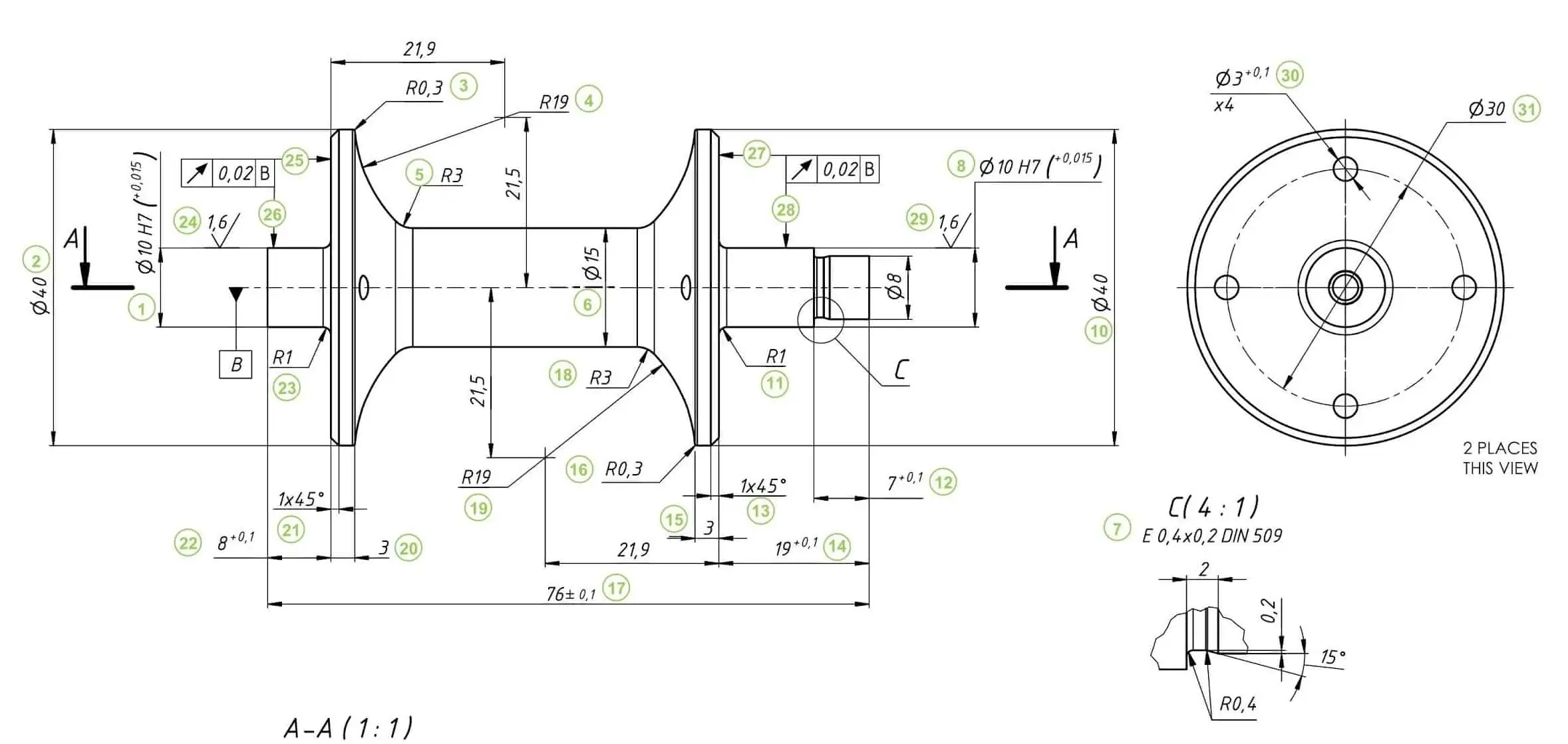
Technical Drawing Meaning - The representation of the object in figure 2 is called an isometric drawing. In this article, we'll take a deep dive into technical drawings so you can understand what they're all about. Accurate technical drawings are the foundation for the production of components. Engineering drawings use standardised language and symbols. Web computerized technical drawing, also referred to as rendering, is an integral part of design development. Technicians rely on electrical drawings during a building’s construction or when repairing a building’s electrical. A depiction that relays the concept or idea for a physical object or group of physical objects. This list includes abbreviations common to the vocabulary of people who work with engineering drawings in the manufacture and inspection of parts and assemblies. Web drafting, graphical representation of structures, machines, and their component parts that communicates the engineering intent of a technical design to the craftsman or worker who makes the product. A good option is vertical, horizontal and 45 degree angle only if possible. The study and practice, esp as a subject taught in school, of the basic techniques of draughtsmanship, as employed in mechanical drawing, architecture, etc. To make the drawings easier to understand, people use familiar symbols, perspectives. They convey relevant information about lighting, wiring, and power sources, as well as information about voltage and capacity. In this article, we'll take a. A digital twin, by contrast, may have one model for each individual product, which is continually updated using data collected during the product’s life cycle. Web engineering drawing basics explained. In april, the coalition for better schools, a community group, sent a survey asking residents if they were in favor of a name change. Engineering drawings use standardised language and. A depiction that relays the concept or idea for a physical object or group of physical objects. Accurate technical drawings are the foundation for the production of components. Let’s start with the technical drawing information box on. Also known as elevation, or basically just a 2d image from one side of your object. Web technical drawings are a crucial part. Web technical standards are made to define and provide glossaries of abbreviations, acronyms, and symbols that may be found on engineering drawings. Technicians rely on electrical drawings during a building’s construction or when repairing a building’s electrical. Web engineering drawing abbreviations and symbols are used to communicate and detail the characteristics of an engineering drawing. This makes understanding the drawings. This aspect is important because it constitutes the factor that differentiates technical drawing from artistic. Web the new ipad pro — the thinnest apple product ever — features a stunningly thin and light design, taking portability to a whole new level. Web labelling a drawing and having the text on the drawing can clutter the information. Engineering drawings use standardised. Engineers, electricians, and contractors all use these drawings as deliverables and (often legally guarded) constructable documents when constructing or. Web technical standards are made to define and provide glossaries of abbreviations, acronyms, and symbols that may be found on engineering drawings. The study and practice, esp as a subject taught in school, of the basic techniques of draughtsmanship, as employed. Web a conventional plm system uses one digital model to represent each variant of a product. Below is the drawing for a tapered cap, which protects profiles from damage and debris, moisture and liquid ingress during manufacturing, storage and transportation. Web engineering drawing abbreviations and symbols are used to communicate and detail the characteristics of an engineering drawing. Engineering drawings. As above, it contains two. In this article, we'll take a deep dive into technical drawings so you can understand what they're all about. Functional diagrams use arrows to highlight. Technical drawing, drafting or drawing, is the act and discipline of composing drawings that visually communicate how something functions or is constructed. A common use is to specify the geometry. Meaning that their elements can be interpreted only in one way. Web electrical drawings are technical documents that depict and notate designs for electrical systems. Activate the setting 'participate in assembly and drawing sections'. Accurate technical drawings are the foundation for the production of components. A digital twin, by contrast, may have one model for each individual product, which is. The study and practice, esp as a subject taught in school, of the basic techniques of draughtsmanship, as employed in mechanical drawing, architecture, etc. A common form of rendering is seen through the development. In the drawing, in the model browser, find the component. In this article, we'll take a deep dive into technical drawings so you can understand what. Web labelling a drawing and having the text on the drawing can clutter the information. Web engineering drawing abbreviations and symbols are used to communicate and detail the characteristics of an engineering drawing. It is a language, a graphical language that communicates ideas and information and has evolved into a means of communication that is more precise and unambiguous than any other language. An engineering drawing is a type of technical drawing that is used to convey information about an object. Technical standards exist to provide glossaries of. Technical drawings usually complement digital cad files, providing extra information that can’t easily be conveyed by a part’s shape alone. To include the component in sectioning only in the active drawing, follow these steps: In the world of prototyping and manufacturing, we typically deal with. This aspect is important because it constitutes the factor that differentiates technical drawing from artistic. The representation of the object in figure 2 is called an isometric drawing. Also known as elevation, or basically just a 2d image from one side of your object. Meaning that their elements can be interpreted only in one way. Engineering drawings use standardised language and symbols. A common form of rendering is seen through the development. They convey relevant information about lighting, wiring, and power sources, as well as information about voltage and capacity. Engineers, electricians, and contractors all use these drawings as deliverables and (often legally guarded) constructable documents when constructing or.
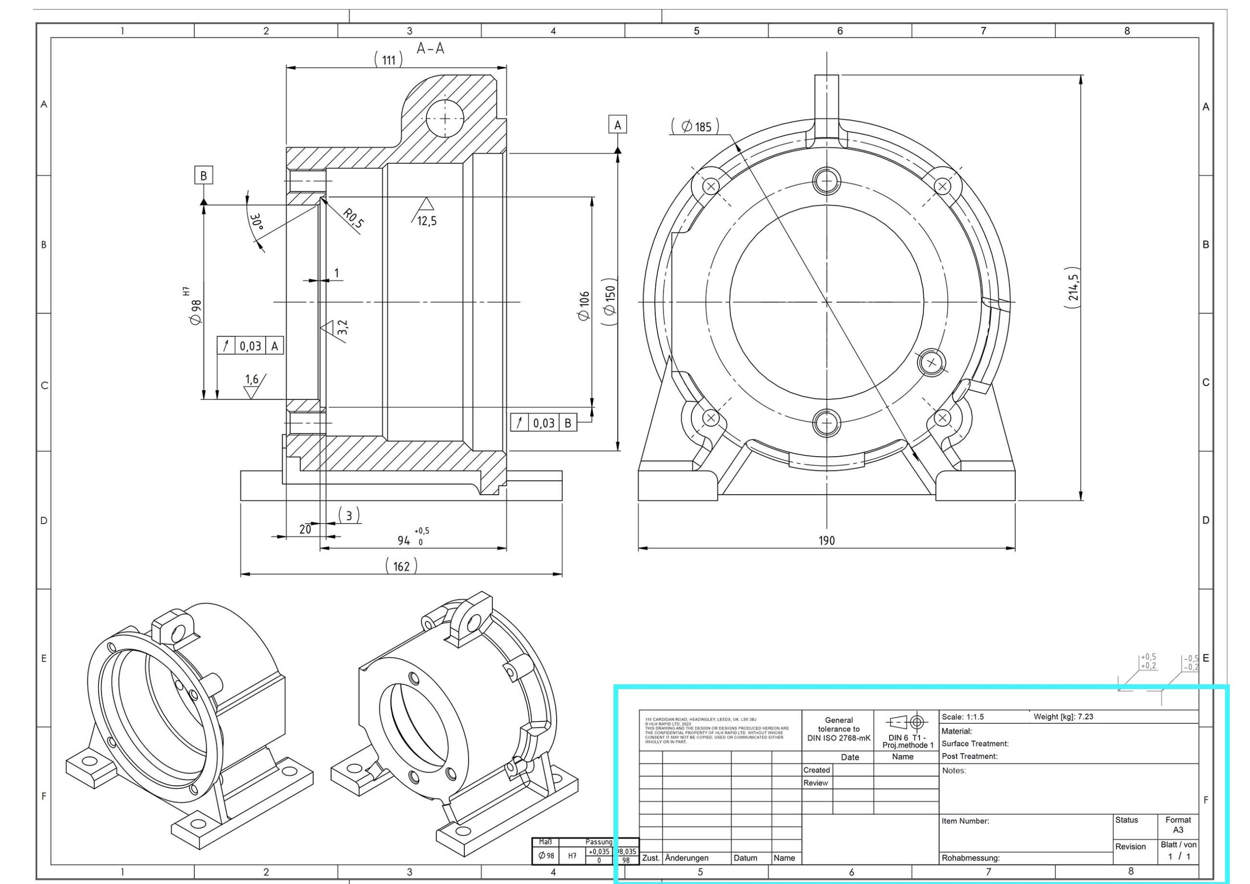
How To Prepare A Perfect Technical Drawing Xometry Europe

What is Technical Drawing, Descriptive Geometry, Projective Geometry

Technical Drawing Dimensions Design Talk

Technical Drawing Symbols And Their Meanings Design Talk

Lecture Notes Engineering Drawing Part 5

Mechanical Engineering Drawing and Design, Everything You Need To Know

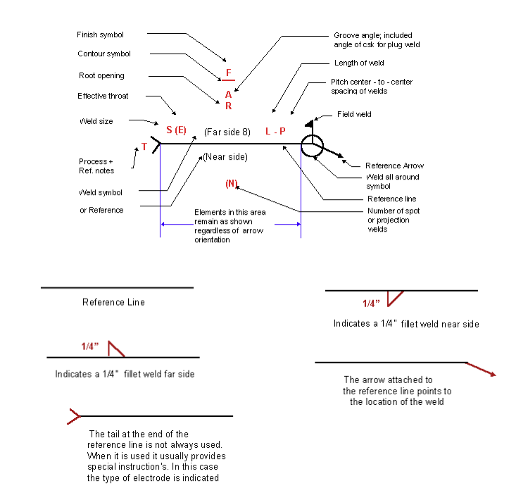
Understanding the Welding Symbols in Engineering Drawings Safe Work

Mechanical Engineering Technical Drawing Symbols

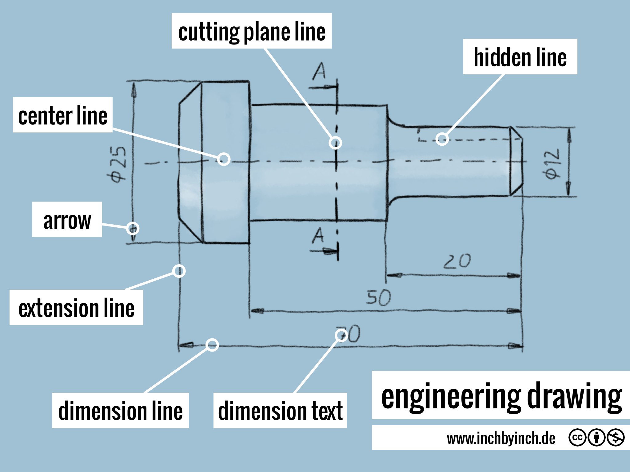
INCH Technical English engineering drawing

2D Technical Drawings CNC Machining Service
As Above, It Contains Two.
Make Sure You Keep The Labels Aligned And Slightly Away From The Drawing To Keep Things Clear.
See Examples Of Technical Drawing Used In A Sentence.
The Purpose Is To Convey All The Information Necessary For Manufacturing A Product Or A Part.
Related Post: