Series Circuit Drawing
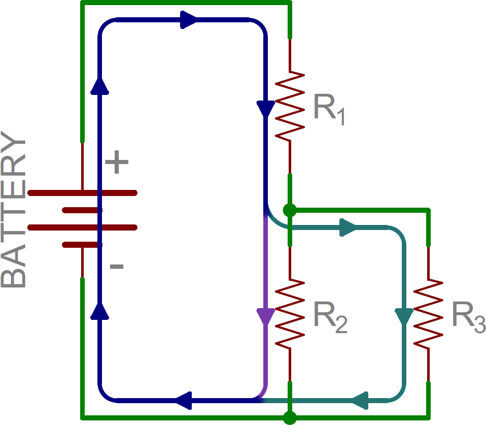
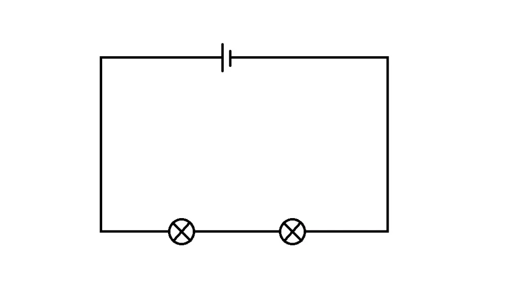
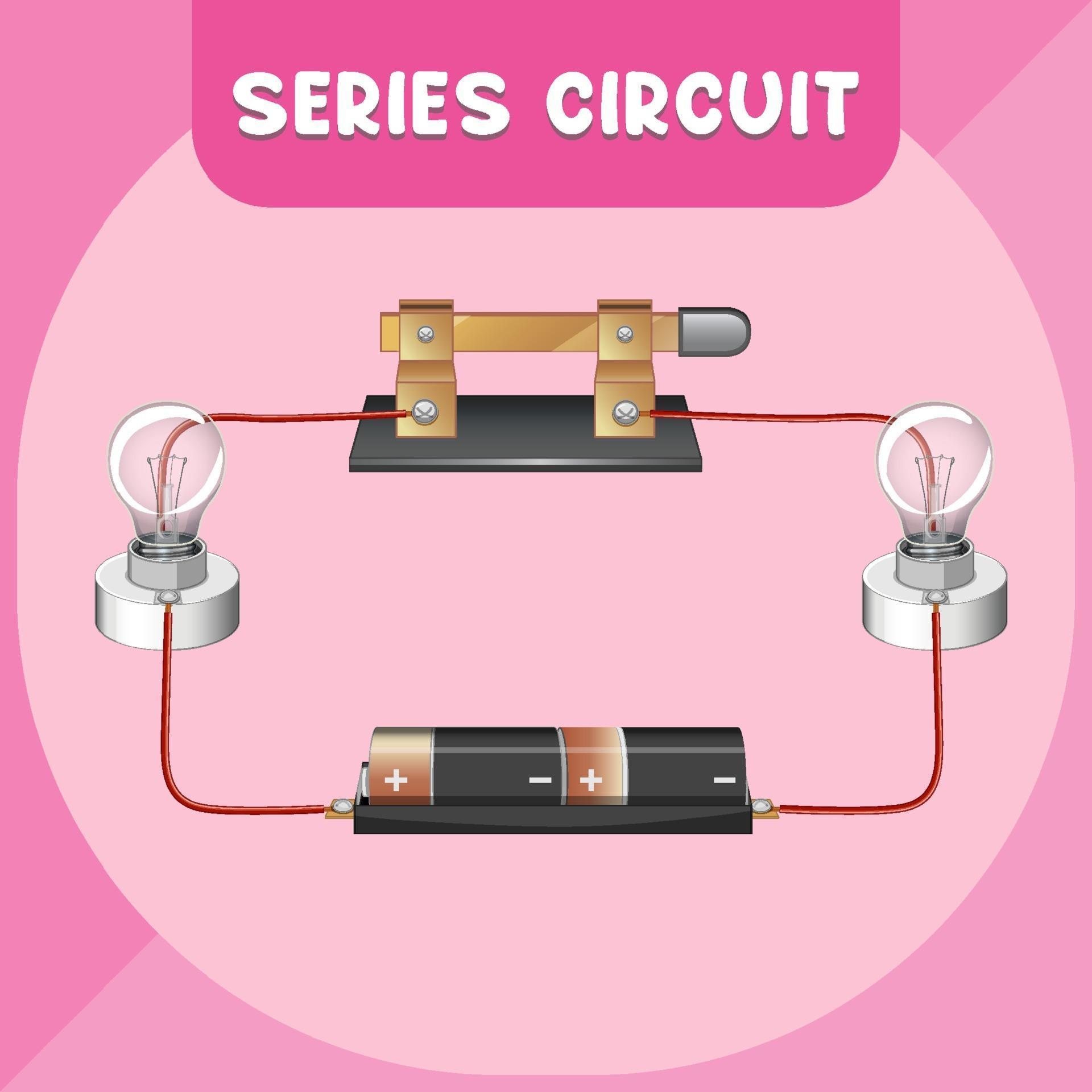
Series Circuit Drawing - Web a circuit in series only has one loop that can be drawn throughout. The electrical connection is not branched in any way and any disruption of the circuit causes the entire circuit to lose current. Circuit, if a lamp breaks or a. Web interpret circuit diagrams and diagram basic circuit elements; But, so is the second resistor, and we now have a total of 2ma. Naturally, current flowing through each resistance is same when the combination is connected across the supply source. Each time there is damage (break) in any one of the resistors, the entire circuit will not function. A series rlc circuit containing a resistance of 12ω, an inductance of 0.15h and a capacitor of 100uf are connected in series across a 100v, 50hz supply. 28 march 2021 | last updated on: Web the schematic drawing is a better way to draw a series circuit. Web a circuit in series only has one loop that can be drawn throughout. But, so is the second resistor, and we now have a total of 2ma. Web this physics video tutorial explains series and parallel circuits. To compare the values of current and electric potential at various locations within a series circuit and to explain the principles that. These series resistors form a single path through which current can flow. Web this physics video tutorial explains series and parallel circuits. To recognize a series circuit, to distinguish it from a parallel circuit, and to construct and/or interpret a schematic diagram of a series circuit. 24 october 2022 by liam cope. Example of a series circuit with multiple components. Resistors are usually represented in a schematic with. Web in a series close series a circuit where one component follows directly from another, eg three bulbs in a row with no junctions are said to be connected in series. Calculate equivalent resistance of resistors in series and apply ohm’s law to resistors in series and apply ohm’s law to resistors. A series rlc circuit containing a resistance of 12ω, an inductance of 0.15h and a capacitor of 100uf are connected in series across a 100v, 50hz supply. Learn how resistors in series increase total resistance, and how to calculate current using ohm's law. Identify exactly what needs to be determined in the problem (identify the unknowns). Understanding series circuits is. Web but what is a series circuit? Identify exactly what needs to be determined in the problem (identify the unknowns). Circuit, if a lamp breaks or a. Is the same in all parts of a series circuit. Batteries are represented in a schematic. Ohm’s law says the first resistor is still going to draw 1ma. Web advantages, disadvantages and examples. Web the schematic drawing is a better way to draw a series circuit. A series rlc circuit containing a resistance of 12ω, an inductance of 0.15h and a capacitor of 100uf are connected in series across a 100v, 50hz supply. The total voltage. Discover how voltage remains constant between elements and how current remains constant throughout the circuit. To compare the values of current and electric potential at various locations within a series circuit and to explain the principles that form the basis of such comparisons. Identify exactly what needs to be determined in the problem (identify the unknowns). Electrical circuits can be. Is the same in all parts of a series circuit. Web in this introduction to series resistance circuits, we will explain these three key principles you should understand: Web part of physics electricity. But, so is the second resistor, and we now have a total of 2ma. Explore the fundamentals of circuits and ohm's law with a focus on series. Electrical circuits can be connected in. Naturally, current flowing through each resistance is same when the combination is connected across the supply source. To compare the values of current and electric potential at various locations within a series circuit and to explain the principles that form the basis of such comparisons. Identify exactly what needs to be determined in the. The current is the same through each component in a series circuit. Each time there is damage (break) in any one of the resistors, the entire circuit will not function. Batteries are represented in a schematic. Identify exactly what needs to be determined in the problem (identify the unknowns). Naturally, current flowing through each resistance is same when the combination. These series resistors form a single path through which current can flow. The electrical connection is not branched in any way and any disruption of the circuit causes the entire circuit to lose current. Resistors are usually represented in a schematic with. Naturally, current flowing through each resistance is same when the combination is connected across the supply source. To recognize a series circuit, to distinguish it from a parallel circuit, and to construct and/or interpret a schematic diagram of a series circuit. Calculate the total circuit impedance, the circuits current, power factor and draw the voltage phasor diagram. A series rlc circuit containing a resistance of 12ω, an inductance of 0.15h and a capacitor of 100uf are connected in series across a 100v, 50hz supply. The total resistance of a series circuit is equal to the sum of the individual resistances. Introduction to series circuits—a series circuit example. It contains plenty of examples, equations, and formulas showing you how to solve it with. This step includes a list of the known values for the problem, since they are labeled in your circuit diagram. In this article, we will take a look at all things related to a series circuit. Draw a clear circuit diagram, labeling all resistors and voltage sources. Design circuits online in your browser or using the desktop application. Web in a series close series a circuit where one component follows directly from another, eg three bulbs in a row with no junctions are said to be connected in series. Batteries are represented in a schematic.
Different Types of Series Circuit Diagrams Explained(AC, DC) ETechnoG

Different Types of Series Circuit Diagrams Explained(AC, DC) ETechnoG

Series Circuit Definition Series Circuit Examples Electrical Academia

Series and Parallel Circuits SparkFun Learn

how to draw a series circuit Wiring Work

Simple Series Circuit Diagram

Series Circuit Diagram EdrawMax Template
What is Series Circuit? « Electrical and Electronic Free Learning Tutorials

Series Parallel Circuit Series Parallel Circuit Examples Electrical

Pictorial Diagram Of Series Circuit
Ohm’s Law Says The First Resistor Is Still Going To Draw 1Ma.
Web Part Of Physics Electricity.
The Current Is The Same Through Each Component In A Series Circuit.
Electrical Circuits Can Be Connected In.
Related Post: