Pid Drawings
Pid Drawings - A p&id uses simple graphics to represent complex processes and convey the flow of material through a process. It includes all piping, instruments, valves, and equipment the system consists of. P&ids are foundational to the maintenance and modification of the process that it graphically represents. P&id is short for “piping and instrumentation diagram”. If you missed the first post in the series, p&id drawings 101, please review it first. Draw p&id diagrams online in the browser with google docs. It serves as a blueprint that outlines the interconnection of piping, equipment, instrumentation, and controls within a process system. Make your own p&id diagrams with this free online drawing tool. Web a piping and instrumentation diagram (p&id) is a comprehensive schematic that illustrates the functional relationship of piping, instrumentation, and system equipment components within a process plant. Web p&id symbols refer to the standard notations and graphical representations used on piping and instrumentation diagrams (p&ids) to depict the components and systems involved in process flows within a facility. (piping & instrumentation diagram) realpars. Web the piping and instrumentation diagram (p&id) is a graphical representation of the actual process plant using various symbols that represent actual equipment. Web here, i have tried to explain p&id and pefs in an easy way. Web in this video, you will learn the basics of piping and instrumentation diagrams (also called p&id drawings).#pipingandinstrumentation. If you missed the first post in the series, p&id drawings 101, please review it first. Web what is a p&id drawing? The p & id includes every mechanical aspect of the plant except stream flows, pipe routing, pipe lengths, pipe fittings, supports, structure & foundations. Make your own p&id diagrams with this free online drawing tool. What a process. How it looks •mechanical drawings: Piping and instrumentation diagrams, or p&ids, are used to create important documentation for process industry facilities. Standard structures located on a p&id include storage tanks, surge tanks, pumps, heat exchangers, reactors, and distillation columns. Web how to read a p&id? Remember that p&ids represent the hardware and software necessary to design, build, and run a. Web a piping and instrumentation diagram, also called p&id, is a diagram used to show a graphical display of a complete system. In the second post of our p&id series, we will be working through an example of a simplified drawing. Web piping and instrumentation diagrams (p&ids) use specific symbols to show the connectivity of equipment, sensors, and valves in. It is a detailed diagram in the process industry that shows all piping including physical sequences of branches, reducers, valves, equipment, instrumentation and control interlocks. Web p&id, short for piping and instrumentation diagram, is a crucial visual representation in the field of engineering. 357k views 3 years ago basic. Web a piping and instrumentation diagram (p&id or pid) is a. In the second post of our p&id series, we will be working through an example of a simplified drawing. Make your own p&id diagrams with this free online drawing tool. Web visual paradigm's p&id tool features a handy diagram editor that allows you to draw p&id diagrams, industrial diagrams, and schematics quickly and easily. It serves as a blueprint that. 357k views 3 years ago basic. Standard structures located on a p&id include storage tanks, surge tanks, pumps, heat exchangers, reactors, and distillation columns. How to read p&id drawing easily. In the second post of our p&id series, we will be working through an example of a simplified drawing. Web in this video, you will learn the basics of piping. Web piping and instrumentation diagrams (p&ids) use specific symbols to show the connectivity of equipment, sensors, and valves in a control system. Every symbol contains letters and a number. It uses symbols to represent process equipment such as sensors and controllers. Through a p&id, you can get the following information: Web p & id diagram. Web in this video, you will learn the basics of piping and instrumentation diagrams (also called p&id drawings).#pipingandinstrumentation #processcontrol #instru. Web a piping and instrumentation diagram (p&id) is a comprehensive schematic that illustrates the functional relationship of piping, instrumentation, and system equipment components within a process plant. It is a detailed diagram in the process industry that shows all piping. Standard structures located on a p&id include storage tanks, surge tanks, pumps, heat exchangers, reactors, and distillation columns. It uses symbols to represent process equipment such as sensors and controllers. How it works •layout drawings: In the second post of our p&id series, we will be working through an example of a simplified drawing. Web what is a p&id drawing? Your list should include all piping elements, including the order and placement of: P&ids are used to develop guidelines and standards for facility operation. Piping & instrumentation diagram explained. These symbols can represent actuators, sensors, and controllers and may be apparent in most, if not all, system diagrams. The p & id includes every mechanical aspect of the plant except stream flows, pipe routing, pipe lengths, pipe fittings, supports, structure & foundations. Web the piping and instrumentation diagram (p&id) is a graphical representation of the actual process plant using various symbols that represent actual equipment. Web what is a p&id drawing? Make your own p&id diagrams with this free online drawing tool. Every symbol contains letters and a number. A p&id uses simple graphics to represent complex processes and convey the flow of material through a process. Reading real world examples | corso systems. It shows the equipment used in the process, and all of the signals required to measure and control the process. Web p&id drawing is a schematic representation of instrumentations, control systems, and pipelines used in any process development plant. Web a piping and instrumentation diagram (p&id or pid) is a detailed diagram in the process industry which shows the piping and process equipment together with the instrumentation and control devices. Web p&id drawings 201: The piping and instrumentation diagram is also known as the process engineering flow scheme, pefs.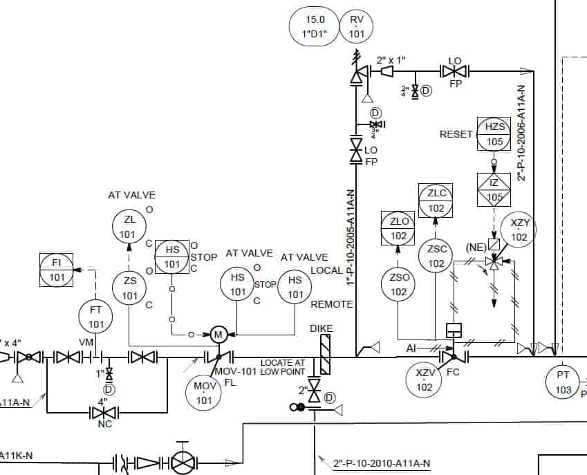
Learn How to Read P&ID Drawings A Complete Guide (2023)
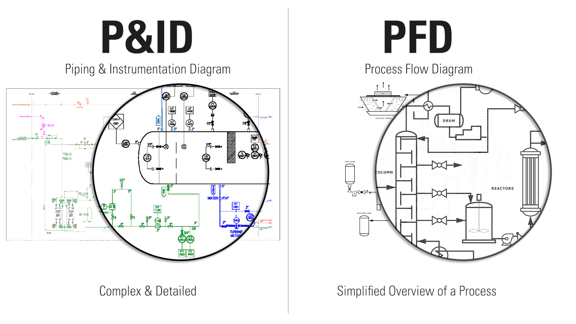
How to Read Oil and Gas P&ID Symbols Kimray

P & ID Diagram. How To Read P&ID Drawing Easily. Piping
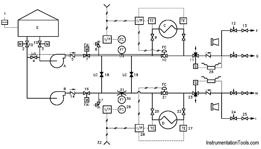
Piping and Instrumentation Documents Instrumentation Tools
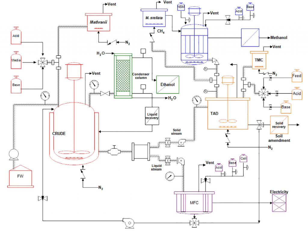
Piping & Instrumentation Diagrams (P&IDs) Punchlist Zero

How to Read P&ID Drawing A Complete Tutorial YouTube
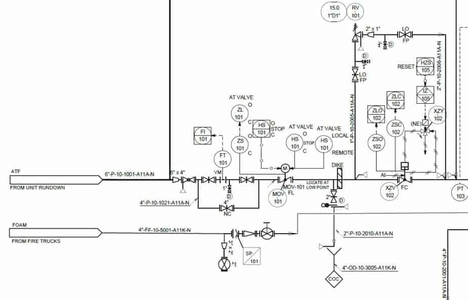
Learn How to Read P&ID Drawings A Complete Guide (2023)

How to Read and Interpret Piping and Instrumentation Diagrams (P&ID

How to Read a P&ID? (Piping & Instrumentation Diagram) YouTube
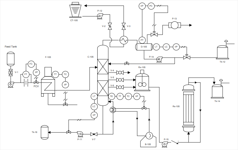
How to Read a P&ID Drawing Quickly and Easily Edraw Max
Web P&Id, Short For Piping And Instrumentation Diagram, Is A Crucial Visual Representation In The Field Of Engineering.
Standard Structures Located On A P&Id Include Storage Tanks, Surge Tanks, Pumps, Heat Exchangers, Reactors, And Distillation Columns.
It Includes All Piping, Instruments, Valves, And Equipment The System Consists Of.
Web Visual Paradigm's P&Id Tool Features A Handy Diagram Editor That Allows You To Draw P&Id Diagrams, Industrial Diagrams, And Schematics Quickly And Easily.
Related Post: