Omni Antenna Radiation Pattern
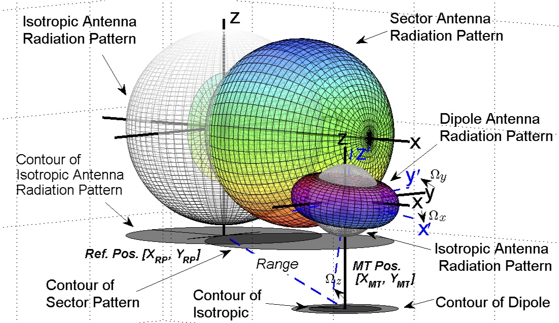
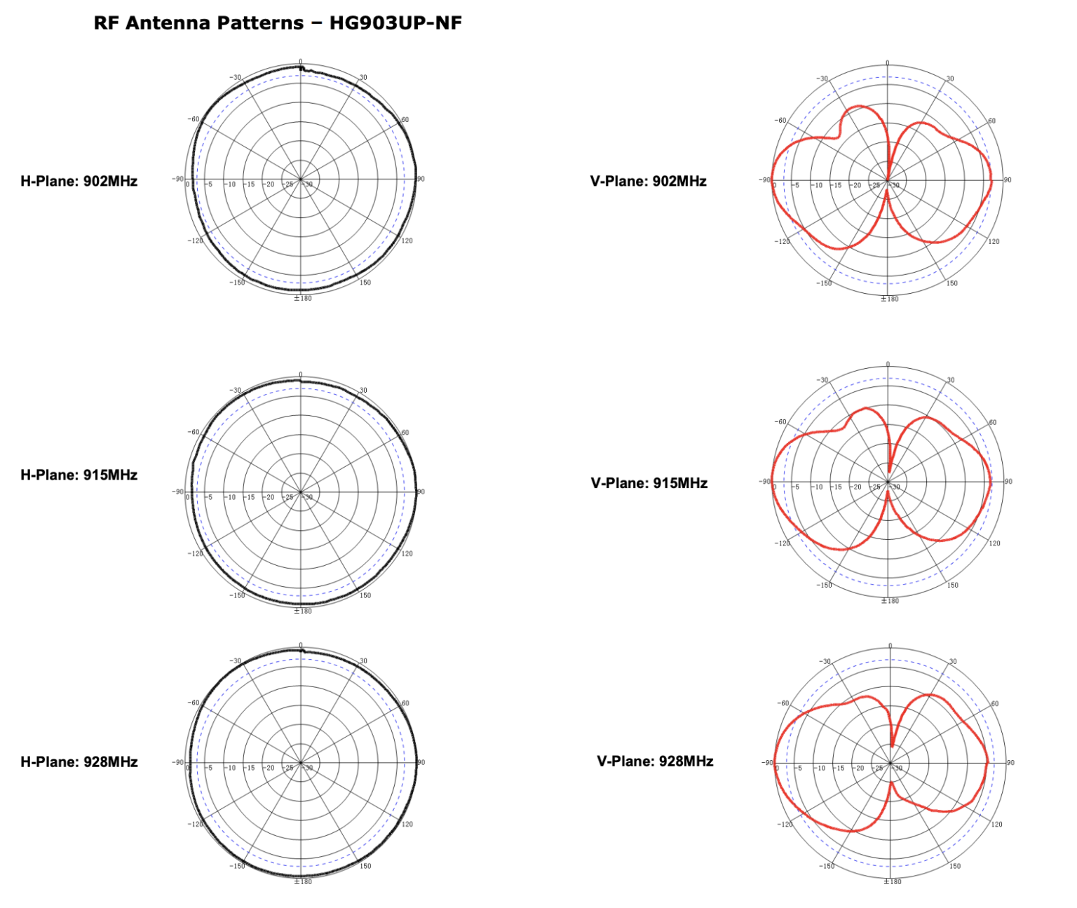
Omni Antenna Radiation Pattern - [1] [2] when graphed in three dimensions (see graph) this radiation pattern is. These are used when coverage is required in all directions (horizontally) from the antenna with varying degrees of vertical coverage. Omnidirectional antennas have a similar radiation pattern. This is analogous to the diminished light as you. Web radiation patterns can be used to better understand how each unifi access point model broadcasts wireless signal. This power variation as a function of the arrival angle is observed in the antenna's far field. The measured radiation pattern at 2.4 ghz for both antennas is shown in fig. The concept of radiation pattern is. Web the top shows the directive pattern of a horn antenna, the bottom shows the omnidirectional pattern of a simple vertical dipole antenna. Gain = efficiency×directivity gain = efficiency × directivity. The above diagrams (figure 1 and figure 2) represent two cuts of a three dimensional radiation pattern, one for azimuth (horizontal) and one for elevation (vertical). Antenna gain incorporates directivity as well as the efficiency of the antenna. Omnidirectional antennas have a similar radiation pattern. These omnidirectional antennas have a doughnut shaped radiation pattern and are ideal for connecting devices. Antenna gain incorporates directivity as well as the efficiency of the antenna. As one moves above the antenna, gain diminishes, eventually becoming green, indicating the presence of little radiation. Web the top shows the directive pattern of a horn antenna, the bottom shows the omnidirectional pattern of a simple vertical dipole antenna. Web these patterns provide system engineers a visual. Gain = efficiency×directivity gain = efficiency × directivity. A pattern may also be defined for a receiving antenna, however, we defer discussion of the receive case to a later section. A directional antenna has a radius of around 45 to 90 degrees, focusing rf energy in a required direction and limiting connectivity to that particular area. The concept of radiation. Antenna gain incorporates directivity as well as the efficiency of the antenna. Web these patterns provide system engineers a visual of how a specific antenna radiates. These antennas provide a 360 degree horizontal radiation pattern. Omnidirectional antennas have a similar radiation pattern. The basic antenna structure is a λ /2 dipole with omnidirectional radiation pattern, operating at 1.4 ghz. A pattern may also be defined for a receiving antenna, however, we defer discussion of the receive case to a later section. The concept of radiation pattern is. Web these patterns provide system engineers a visual of how a specific antenna radiates. These are used when coverage is required in all directions (horizontally) from the antenna with varying degrees of. From this simulation we can see that. Antenna gain incorporates directivity as well as the efficiency of the antenna. Web the reconstructed pattern does not vary. These are used when coverage is required in all directions (horizontally) from the antenna with varying degrees of vertical coverage. These omnidirectional antennas have a doughnut shaped radiation pattern and are ideal for connecting. We can see from these three images that the radiation pattern of poynting’s omni 292 antenna is almost perfectly uniform in 3d space across all of the frequencies, meaning a perfectly balanced beam is sent out in all directions from the antenna toward the horizon. This power variation as a function of the arrival angle is observed in the antenna's. Radiations from an antenna are plotted as a function of radial distance and angular position from the antenna. Web commonly known as an omnidirectional antennas, all dipole antennas have a generalized radiation pattern. We can see from these three images that the radiation pattern of poynting’s omni 292 antenna is almost perfectly uniform in 3d space across all of the. A directional antenna has a radius of around 45 to 90 degrees, focusing rf energy in a required direction and limiting connectivity to that particular area. Web this type of antenna patterns is useful when you want to look into the antenna performance in the horizontal or vertical plane. Web the top shows the directive pattern of a horn antenna,. Web the top shows the directive pattern of a horn antenna, the bottom shows the omnidirectional pattern of a simple vertical dipole antenna. As one moves above the antenna, gain diminishes, eventually becoming green, indicating the presence of little radiation. The basic antenna structure is a λ /2 dipole with omnidirectional radiation pattern, operating at 1.4 ghz. The concept of. [1] [2] when graphed in three dimensions (see graph) this radiation pattern is. The basic antenna structure is a λ /2 dipole with omnidirectional radiation pattern, operating at 1.4 ghz. Radiations from an antenna are plotted as a function of radial distance and angular position from the antenna. Web parabolic antennas (such as those used in satellite television receivers) have a typical directive gain (or simply gain) of 37.5 db. Web omnidirectional dipole antennas. Antenna gain incorporates directivity as well as the efficiency of the antenna. These omnidirectional antennas have a doughnut shaped radiation pattern and are ideal for connecting devices that are on the same plane and to either side of each other. A pattern may also be defined for a receiving antenna, however, we defer discussion of the receive case to a later section. The proposed antenna consists of a circular patch with eight open slots, eight shorted metal pins, and a central feed coaxial probe. In mobile applications, omnidirectional dipole antennas fail to. Web this type of antenna patterns is useful when you want to look into the antenna performance in the horizontal or vertical plane. From this simulation we can see that. Gain = efficiency×directivity gain = efficiency × directivity. This power variation as a function of the arrival angle is observed in the antenna's far field. The above diagrams (figure 1 and figure 2) represent two cuts of a three dimensional radiation pattern, one for azimuth (horizontal) and one for elevation (vertical). The given figure is a three dimensional radiation pattern for an omni directional pattern.
Omnidirectional Antenna Radiation Pattern

Omni Antenna Radiation Pattern

Omnidirectional Antenna Radiation Patterns Explained MP Antenna

2 An example of omnidirectional antenna radiation pattern Download
Wireless Communication

Omnidirectional Antenna Radiation Pattern ANTENA BARU

Radiation patterns of the ±45° SP reconfigurable omnidirectional

How To Read An Antenna Chart Gristle King A Guide to DePIN

Omnidirectional Antenna Radiation Patterns Explained MP Antenna

Radiation patterns for (a) directional and (b) omnidirectional
Efficiency Accounts For The Actual Losses Of A Particular.
Web A Radiation Pattern Defines The Variation Of The Power Radiated By An Antenna As A Function Of The Direction Away From The Antenna.
Web Radiation Pattern In 3D.
Automatic Discarding Of Data Points
Related Post: