Inverted V Radiation Pattern
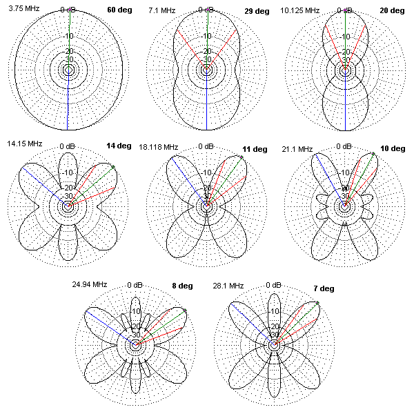
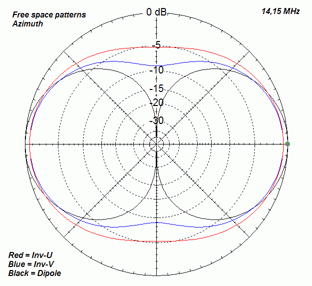
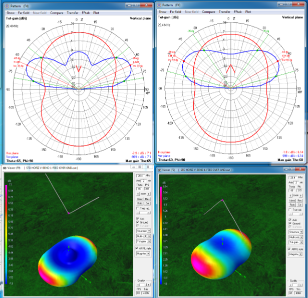
Inverted V Radiation Pattern - Excellent antenna is a resonant 1⁄2 λ horizontal dipole at 0.15 λ height. Due to variation of high frequency as well as distance between transmitting and receiving stations, it is not always feasible. Web the depicted radiation patterns display both the azimuth and the elevation planes sections of the 3d radiation pattern for 20m and 40m hf bands. 20 meter dipole v at 42 feet with wires sloping down at 30 degrees. Web turns out that if you use a long multiband antenna as an inverted v it really changes the radiation pattern. 75m resonant loop is poor performer for 40m. The lobes contract quite badly and the radiation angle goes up dramatically. Web that means the ends will be angled in an inverted v configuration, so what does that do to our radiation pattern? Use a modified version from zs6, w0 or ve3 (none are “all” band) see later slide. At 15° above the horizon for distance. Due to variation of high frequency as well as distance between transmitting and receiving stations, it is not always feasible. Typical amateur radio inverted vee installed on roof. Web following is a series of dipole radiation pattern plots, produced by a popular antenna modeling program. Good performance from 0.1λ to 0.25λ. At 15° above the horizon for distance. Here is a plot of our 20m dipole, now in a v configuration with the two ends each sloping at 30 degrees: We have already discussed previously that in long wire antenna the length of. 20 meter dipole v at 42 feet with wires sloping down at 30 degrees. Web yet another characteristic is the radiation pattern. Excellent antenna is. We have already discussed previously that in long wire antenna the length of. 20 meter dipole v at 42 feet with wires sloping down at 30 degrees. Good performance from 0.1λ to 0.25λ. Web beam steerable hf inverted v dipole antenna abstract: Web yet another characteristic is the radiation pattern. The lobes contract quite badly and the radiation angle goes up dramatically. Web if you start with the inverted v model, the instructions result in the wires being arranged as in figure 9.8 which offsets the center of the antenna 60.35 feet to the right along the x. 8.19 dbi of gain and take off angle at 25 degrees. Web. At 15° above the horizon for distance. The first plot below shows a dipole at an elevation of two. A standard dipole generates a horizontal ratiation pattern in the shape of a figure 8, with maximum radiation broadside to the. 20 meter dipole v at 42 feet with wires sloping down at 30 degrees. Use a modified version from zs6,. 20 meter dipole v at 42 feet with wires sloping down at 30 degrees. Excellent antenna is a resonant 1⁄2 λ horizontal dipole at 0.15 λ height. Web despite the slight loss of gain compared to a horizontal dipole, the inverted v antenna offers a hidden gain due to its higher mounting point. Web that means the ends will be. 8.19 dbi of gain and take off angle at 25 degrees. Typical amateur radio inverted vee installed on roof. The lobes contract quite badly and the radiation angle goes up dramatically. Web following is a series of dipole radiation pattern plots, produced by a popular antenna modeling program. Use a modified version from zs6, w0 or ve3 (none are “all”. Vertical antennas do not generate a nvis pattern. Web turns out that if you use a long multiband antenna as an inverted v it really changes the radiation pattern. 20 meter dipole v at 42 feet with wires sloping down at 30 degrees. The lobes contract quite badly and the radiation angle goes up dramatically. Web yet another characteristic is. Here is a plot of our 20m dipole, now in a v configuration with the two ends each sloping at 30 degrees: Vertical antennas do not generate a nvis pattern. Web that means the ends will be angled in an inverted v configuration, so what does that do to our radiation pattern? The lobes contract quite badly and the radiation. Web that means the ends will be angled in an inverted v configuration, so what does that do to our radiation pattern? A standard dipole generates a horizontal ratiation pattern in the shape of a figure 8, with maximum radiation broadside to the. Vertical antennas do not generate a nvis pattern. The lobes contract quite badly and the radiation angle. Web that means the ends will be angled in an inverted v configuration, so what does that do to our radiation pattern? Web yet another characteristic is the radiation pattern. Here is a plot of our 20m dipole, now in a v configuration with the two ends each sloping at 30 degrees: 75m resonant loop is poor performer for 40m. Web beam steerable hf inverted v dipole antenna abstract: Web following is a series of dipole radiation pattern plots, produced by a popular antenna modeling program. At 15° above the horizon for distance. A standard dipole generates a horizontal ratiation pattern in the shape of a figure 8, with maximum radiation broadside to the. Due to variation of high frequency as well as distance between transmitting and receiving stations, it is not always feasible. 20 meter dipole v at 42 feet with wires sloping down at 30 degrees. We have already discussed previously that in long wire antenna the length of. Web turns out that if you use a long multiband antenna as an inverted v it really changes the radiation pattern. Typical amateur radio inverted vee installed on roof. Just see how similar both the antennas are. Web despite the slight loss of gain compared to a horizontal dipole, the inverted v antenna offers a hidden gain due to its higher mounting point. The first plot below shows a dipole at an elevation of two.[Get 31+] Inverted V Dipole Antenna Radiation Pattern

InvertedV Dipole (11m), HamSphere 5.0 Shop

Charts of radiation pattern Download Scientific Diagram

G5RV radiation pattern question Page 1

dipole, invertedv, invertedu

Omnidirectional Antenna Radiation Patterns Explained MP Antenna

radiation pattern How Does the Performance of an Inverted V Dipole

FM 2418 Tactical SingleChannel Radio Communications Techniques

Centerfed Horizontal Vdipole

EndGrounded Inverted V YouTube
Web The Depicted Radiation Patterns Display Both The Azimuth And The Elevation Planes Sections Of The 3D Radiation Pattern For 20M And 40M Hf Bands.
Good Performance From 0.1Λ To 0.25Λ.
The Lobes Contract Quite Badly And The Radiation Angle Goes Up Dramatically.
Vertical Antennas Do Not Generate A Nvis Pattern.
Related Post: