Inverted V Antenna Radiation Pattern
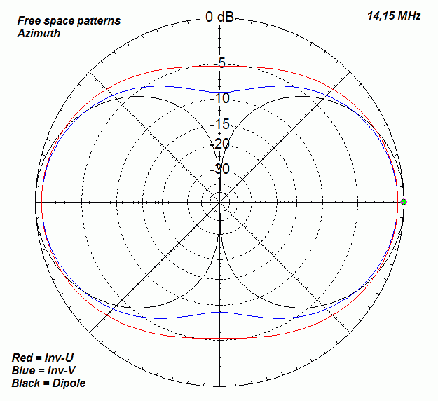
Inverted V Antenna Radiation Pattern - If you start with the inverted v model, the instructions result in the wires being arranged as in figure 9.8 which offsets. Web the pattern of antenna radiation is dependant on wavelength height, the distance in wavelengths above the ground. Decibels (db) = 10 log (power ratio) impedance = ratio of voltage to current. Use a calculator like this one to calculate the length of. Web the radiation pattern shows how antennas distribute energy in space. The general rule is to position an antenna is as high as. Web the depicted radiation patterns display both the azimuth and the elevation planes sections of the 3d radiation pattern for 20m and 40m hf bands. The major part of the radiated field, which covers a larger area, is the main lobe or major lobe. Typical amateur radio inverted vee installed on roof. Web here, the radiation pattern has main lobe, side lobes and back lobe. Web here, the radiation pattern has main lobe, side lobes and back lobe. Web the pattern of antenna radiation is dependant on wavelength height, the distance in wavelengths above the ground. If you start with the inverted v model, the instructions result in the wires being arranged as in figure 9.8 which offsets. The preceding two sets of notes have. The angle of the inverted v antenna is not critical, but a broad angle of around 60 degrees can provide optimal feed impedance. Web an inverted v is about as close as you're gonna get to an isotropic, that being a point in space which radiates out spherically exactly the same in all directions. Web the pattern of antenna radiation. Web the depicted radiation patterns display both the azimuth and the elevation planes sections of the 3d radiation pattern for 20m and 40m hf bands. We have already discussed previously that in long wire antenna the length of the conductor. Web all three antennas are resonant at 3.5 mhz (using awg #12 or 0.0808 diameter wire). Web the pattern of. Web here, the radiation pattern has main lobe, side lobes and back lobe. The preceding two sets of notes have developed a data compendium on. Typical amateur radio inverted vee installed on roof. Web the pattern of antenna radiation is dependant on wavelength height, the distance in wavelengths above the ground. The general rule is to position an antenna is. Typical amateur radio inverted vee installed on roof. The preceding two sets of notes have developed a data compendium on. Web the paper provides effective solution for adjusting beam take off angle ± 30 degree electronically without physical height variation of hf antenna. Web the following material supports the book antenna modeling for beginners. Web here, the radiation pattern has. Just see how similar both the antennas are. The preceding two sets of notes have developed a data compendium on. Tilting angle for antenna radiation pattern has been controlled by gradually varying the capacitor value positioned at one end of dipole keeping fixed value of parallel inductor. Web the depicted radiation patterns display both the azimuth and the elevation planes. Web the paper provides effective solution for adjusting beam take off angle ± 30 degree electronically without physical height variation of hf antenna. Good performance from 0.1λ to 0.25λ. An inverted vee radiates and receives very much like a horizontal dipole. Just see how similar both the antennas are. Web the radiation pattern shows how antennas distribute energy in space. We have already discussed previously that in long wire antenna the length of the conductor. The general rule is to position an antenna is as high as. Web the pattern of antenna radiation is dependant on wavelength height, the distance in wavelengths above the ground. Web the following material supports the book antenna modeling for beginners. Web the radiation pattern. Just see how similar both the antennas are. Typical amateur radio inverted vee installed on roof. We have already discussed previously that in long wire antenna the length of the conductor. The general rule is to position an antenna is as high as. If you start with the inverted v model, the instructions result in the wires being arranged as. An inverted vee radiates and receives very much like a horizontal dipole. Web a standard dipole generates a horizontal ratiation pattern in the shape of a figure 8, with maximum radiation broadside to the antenna. Just see how similar both the antennas are. Web the pattern of antenna radiation is dependant on wavelength height, the distance in wavelengths above the. I am still working on this page, so sorry about the spelling, english and the science ! The preceding two sets of notes have developed a data compendium on. Web inverted vee antennas are horizontally polarized and have a similar pattern compared to a traditional horizontal dipole. Tilting angle for antenna radiation pattern has been controlled by gradually varying the capacitor value positioned at one end of dipole keeping fixed value of parallel inductor. The general rule is to position an antenna is as high as. Web an inverted v is about as close as you're gonna get to an isotropic, that being a point in space which radiates out spherically exactly the same in all directions. The major part of the radiated field, which covers a larger area, is the main lobe or major lobe. We have already discussed previously that in long wire antenna the length of the conductor. Web a standard dipole generates a horizontal ratiation pattern in the shape of a figure 8, with maximum radiation broadside to the antenna. Good performance from 0.1λ to 0.25λ. Typical amateur radio inverted vee installed on roof. An inverted vee radiates and receives very much like a horizontal dipole. Use a calculator like this one to calculate the length of. Web here, the radiation pattern has main lobe, side lobes and back lobe. Web excellent antenna is a resonant 1⁄2 λ horizontal dipole at 0.15 λ height. The angle of the inverted v antenna is not critical, but a broad angle of around 60 degrees can provide optimal feed impedance.[Download 36+] Inverted V Dipole Antenna Radiation Pattern

dipole, invertedv, invertedu

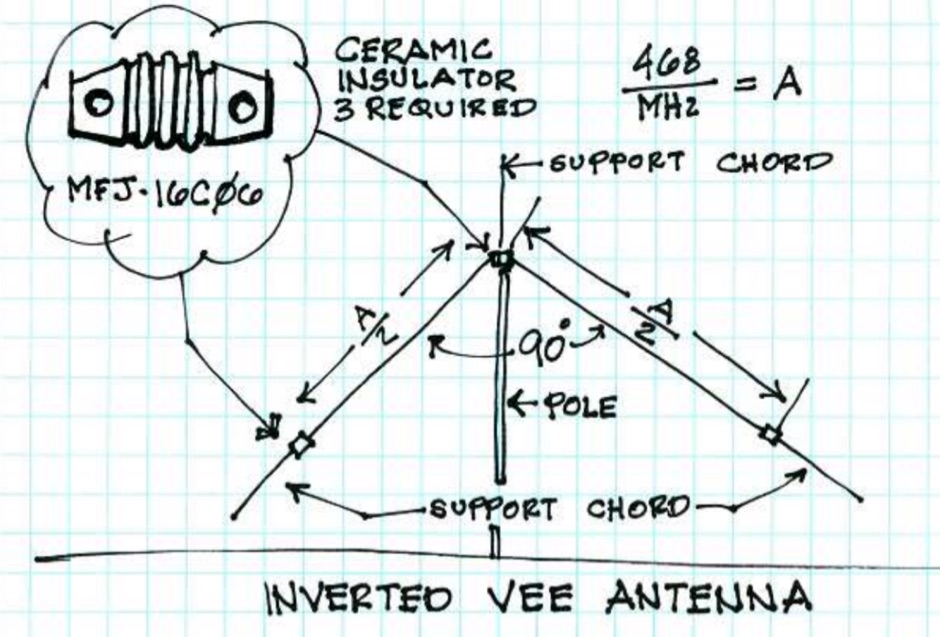
How to Build an Inverted V Dipole Antenna? Johnson's Techworld

Basic Inverted V Antenna The

Loop Antenna Radiation Pattern

FM 2418 Tactical SingleChannel Radio Communications Techniques
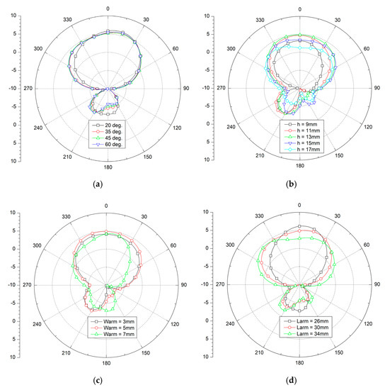
![[Download 36+] Inverted V Dipole Antenna Radiation Pattern](https://www.mdpi.com/electronics/electronics-08-00637/article_deploy/html/images/electronics-08-00637-g002.png)
[Download 36+] Inverted V Dipole Antenna Radiation Pattern

BBTD Inverted V Pyramid Large Size Radiation Patterns Antennas, Ham

Electronics Free FullText A Compact Crossed InvertedV Antenna

radiation pattern How Does the Performance of an Inverted V Dipole
Just See How Similar Both The Antennas Are.
Web The Radiation Pattern Shows How Antennas Distribute Energy In Space.
If You Start With The Inverted V Model, The Instructions Result In The Wires Being Arranged As In Figure 9.8 Which Offsets.
Web Practical Basic Nvis Antennas:
Related Post: