Door Closer Installation Template
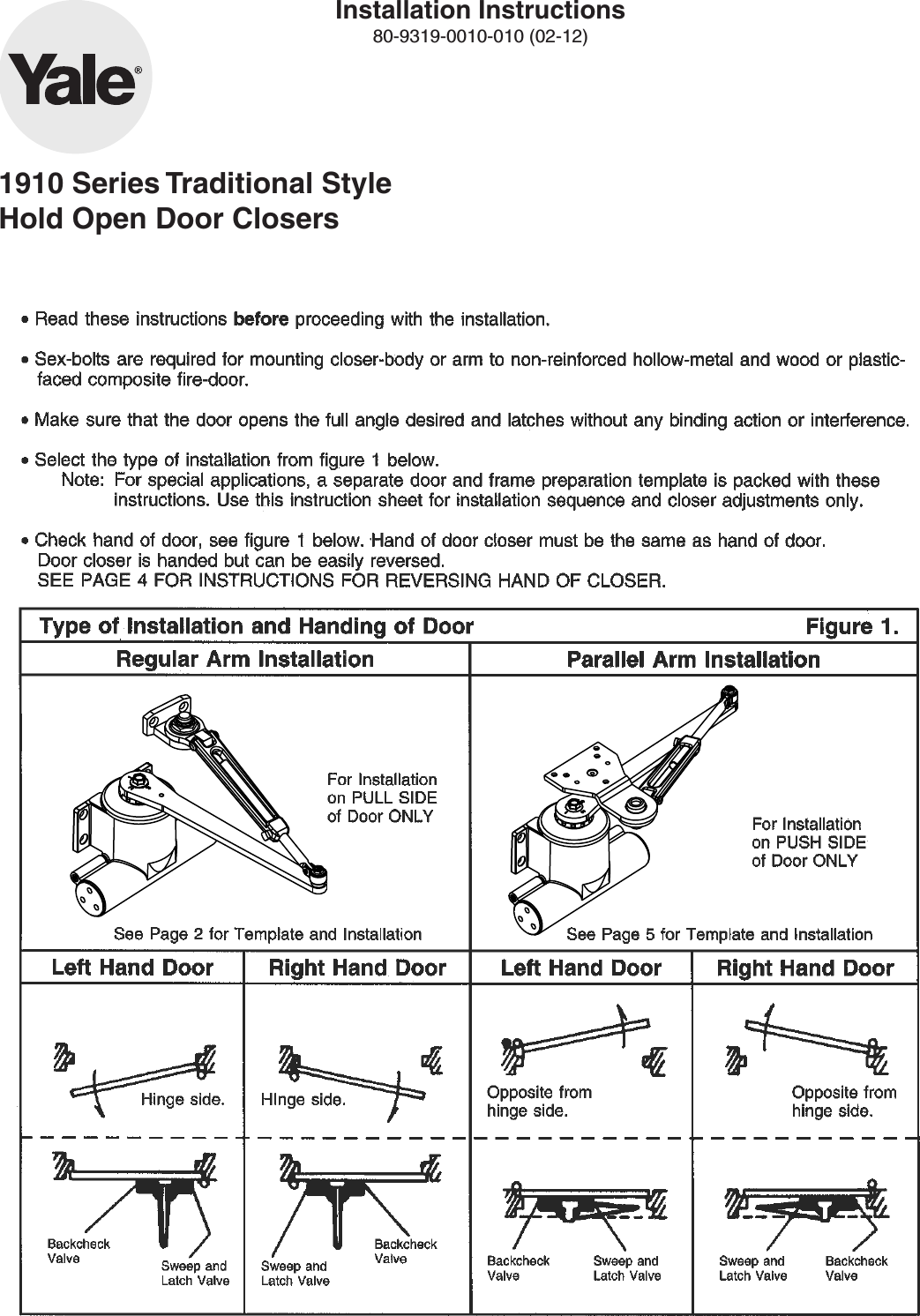
Door Closer Installation Template - For special applications a separate door and frame preparation template is packed with these instructions. Use this instruction sheet for installation sequence and closer. Desired, prepare the frame to specifications. Web left hand door 1. Use dimensions in chart and illustration above to mark location of attaching on door and frame prepare holes. In those cases, use this instruction sheet for installation. How to install briton door closers. Web fold or cut upper (241mm) corner illustrated on template and align template with the hinge edge of door. 2, 3, 4 and 5. Standard mount (pull side) maximum door width. Standard mount (pull side) maximum door width. In those cases, use this instruction sheet for installation. Place cover over closer ond hold ogainst door while tightening cover screws firmly. For special applications, a separate door and frame preparation template is packed with these instructions. The voltage shown on the track cover plate must match voltage. For special applications a separate door and frame preparation template is packed with these instructions. How to install briton door closers. Standard mount (pull side) maximum door width. At the “frame stop *121 to 180 7 line” fold toward you and attach. Desired, prepare the frame to specifications. For special applications a separate door and frame preparation template is packed with these instructions. Web fold or cut upper (241mm) corner illustrated on template and align template with the hinge edge of door. Arm de at adout o the orm will appear to fosten with arm shaft. This includes a clickable index at the front, and includes every metal. Desired, prepare the frame to specifications. 13/ 4” (44mm) 1115/ 16” (304mm) door edge. Web size “1” closer is equivelent of a “bf” closer. Place cover over closer ond hold ogainst door while tightening cover screws firmly. Web left hand door 1. Supplied to door frame (24v or 120v). Web door closer series 416 installation instruction. How to install briton door closers. Installation instructions select degree of door. 13/ 4” (44mm) 1115/ 16” (304mm) door edge. 2, 3, 4 and 5. Closer is installed on pull/hinge side of door. Web size “1” closer is equivelent of a “bf” closer. Web installation template for enforcer door closer. Web view and download lcn 4040xp installation instructions online. For special applications, a separate door and frame preparation template is packed with these instructions. Web door closer series 416 installation instruction. For special applications a separate door and frame preparation template is packed with these instructions. Supplied to door frame (24v or 120v). How to install briton door closers. For special applications a separate door and frame preparation template is packed with these instructions. Web view and download lcn 4040xp installation instructions online. Place cover over closer ond hold ogainst door while tightening cover screws firmly. 2, 3, 4 and 5. Use this instruction sheet for installation sequence and closer. For special applications a separate door and frame preparation template is packed with these instructions. Installation instructions select degree of door. Desired, prepare the frame to specifications. For special applications, a separate door and frame preparation template is packed with these instructions. For special applications a separate door and frame preparation template is packed with these instructions. For special applications a separate door and frame preparation template is packed with these instructions. For special applications, a separate door and frame preparation template is packed with these instructions. How to install briton door closers. Web installation template for enforcer door closer. Use this instruction sheet for installation sequence and closer. Web fold or cut upper (241mm) corner illustrated on template and align template with the hinge edge of door. Desired, prepare the frame to specifications. For special applications a separate door and frame preparation template is packed with these instructions. Web door closer series 416 installation instruction. Supplied to door frame (24v or 120v). 4040xp door opening system pdf manual download. For special applications, a separate door and frame preparation template is packed with these instructions. Installation instructions select degree of door. Web size “1” closer is equivelent of a “bf” closer. Closer is installed on pull/hinge side of door. Use dimensions in chart and illustration above to mark location of attaching on door and frame prepare holes. Standard mount (pull side) maximum door width. Use this instruction sheet for installation sequence and closer. 13/ 4” (44mm) 1115/ 16” (304mm) door edge. For special applications a separate door and frame preparation template is packed with these instructions. The voltage shown on the track cover plate must match voltage.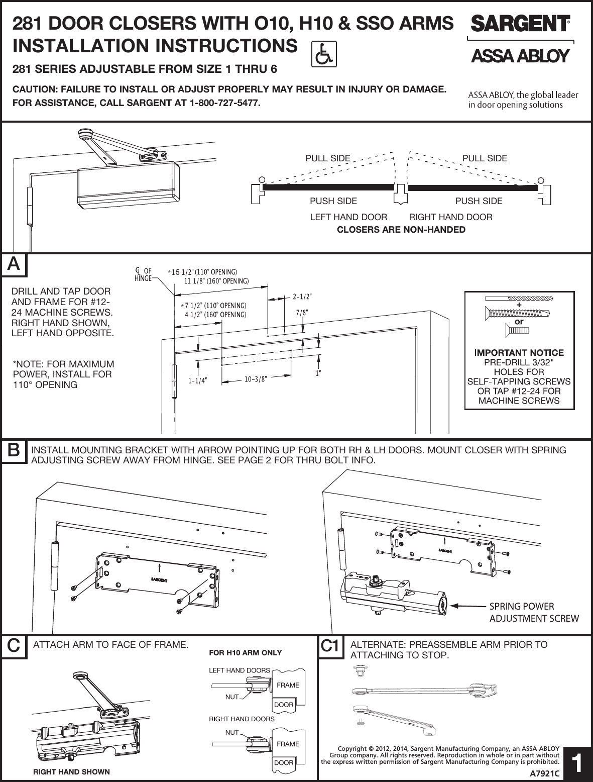
Sargent Installation Instructions For 281 Door Closers With O10/H10/SSO

Door Closer Installation Template

Door Closer Installation Template
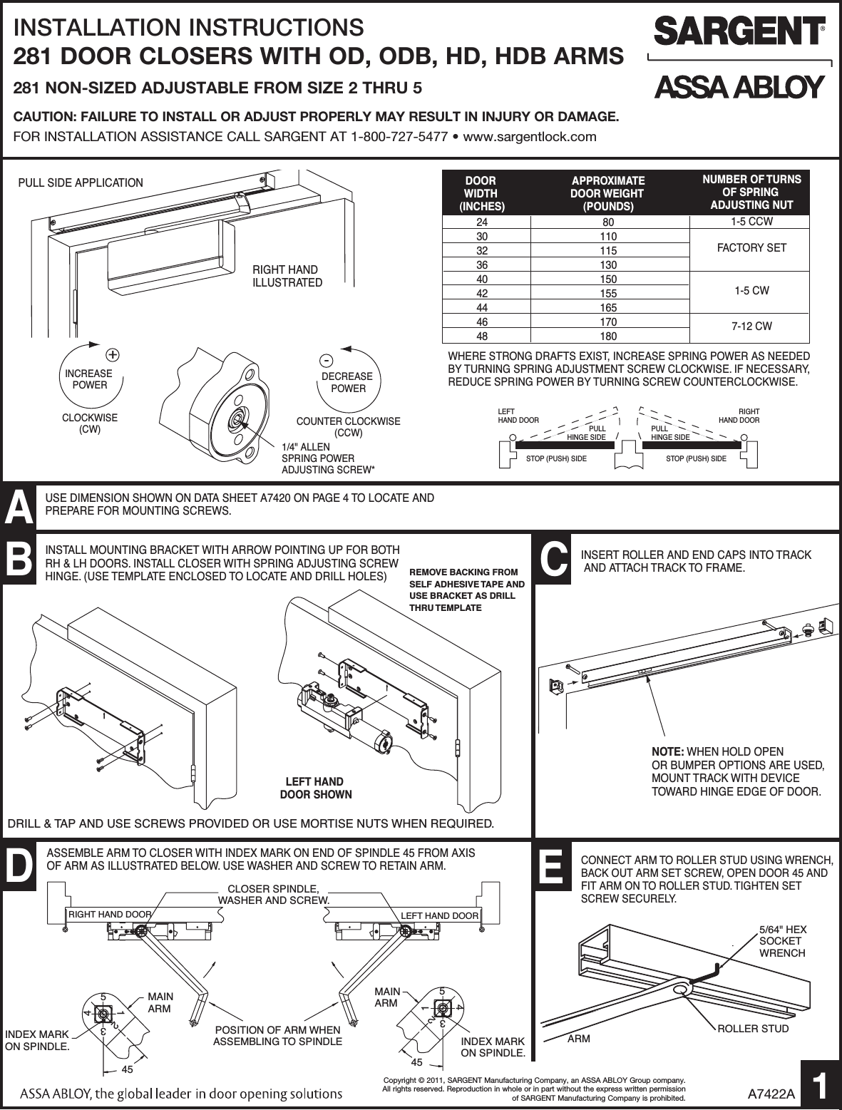
Door Closer Installation Template
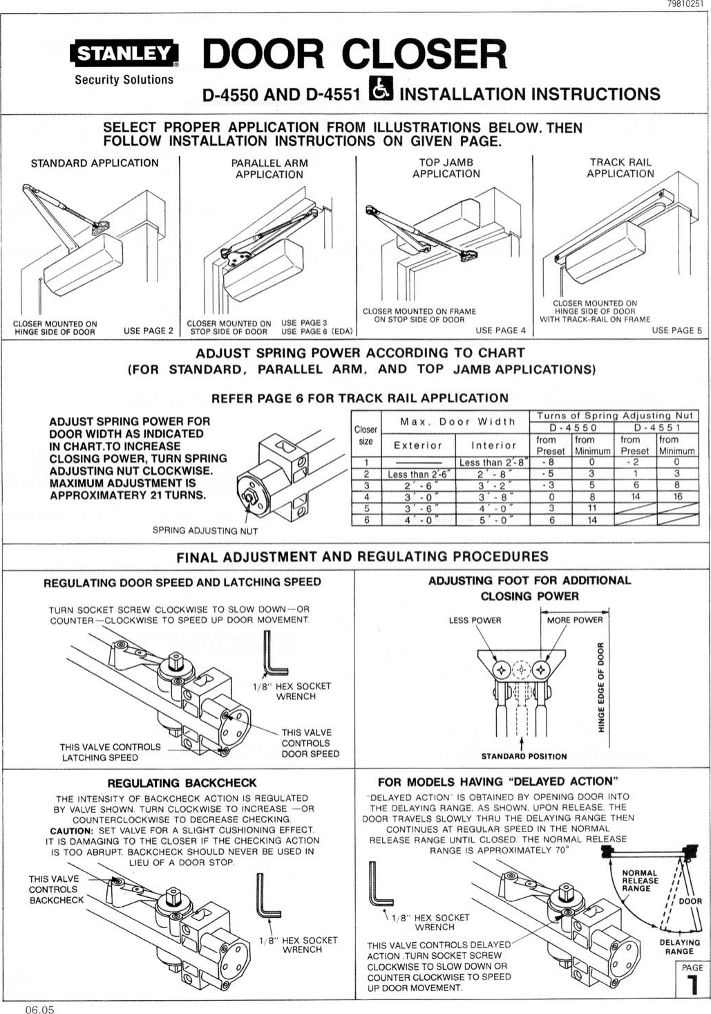
Stanley Security Microsoft 4550 D 4550, 4551 Door Closer Installation
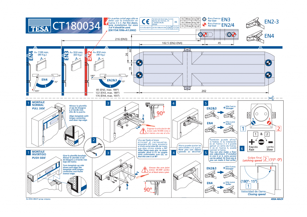
How to install a door closer Puertas Cortafuegos Asturmadi Doors

Installation Guide for Panic Bars, Door Closers and Exit Accessories
Door Closer Installation Template
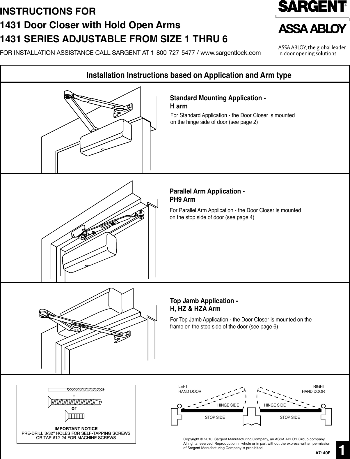
Sargent Instructions For Installing 1431 Series Door Closers (with Hold
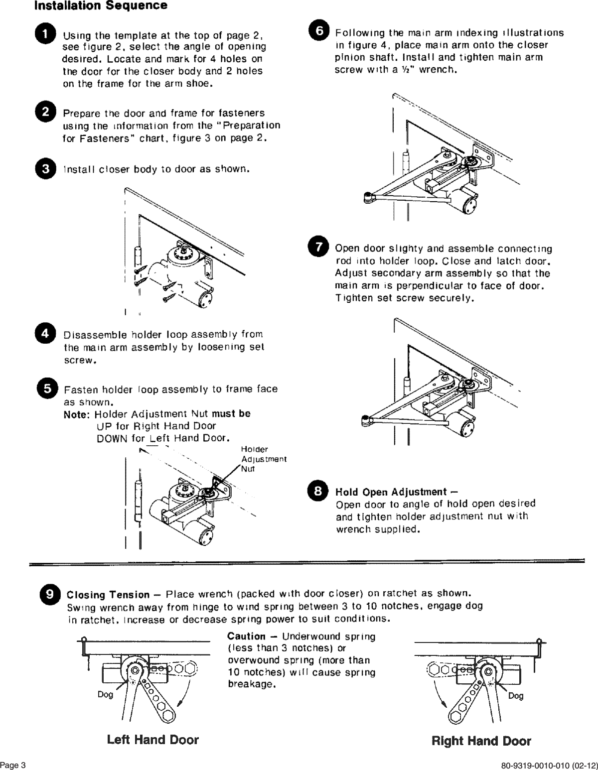
Door Closer Installation Manual
Arm De At Adout O The Orm Will Appear To Fosten With Arm Shaft.
Web Installation Template For Enforcer Door Closer.
Web View And Download Lcn 4040Xp Installation Instructions Online.
At The “Frame Stop *121 To 180 7 Line” Fold Toward You And Attach.
Related Post: