Diffraction Pattern
Diffraction Pattern - Web the angular spacing of the features in the diffraction pattern is inversely proportional to the dimensions of the object causing the diffraction. In contrast, a diffraction grating produces evenly spaced lines that dim slowly on either side of the center. Web it measures the degradation of the diffraction image quality due to radiation damage and compton scattering with respect to the diffraction from an undamaged molecule (elastic signal only; Note that the central maximum is larger than those on either side, and that the intensity decreases rapidly on either side. According to huygens’ principle, the aperture or slit diffracting the waves becomes the secondary source of waves. Understand why this occurs and its significance in measuring light waves. Web tailoring electron vortex beams with customizable intensity patterns by electron diffraction holography. It happens to light waves, sound waves and water waves. This bending often causes waves to interfere with themselves, creating diffraction patterns. A single slit produces an interference pattern characterized by a broad central maximum with narrower and dimmer maxima to the sides. This bending often causes waves to interfere with themselves, creating diffraction patterns. Web diffraction patterns are obtained by focusing a parallel electron beam on the sample in the same way as in the imaging mode. Now let us use the huygens principle to analyze a (slightly) more complex problem: Experiment with diffraction through elliptical, rectangular, or. In order to have. Web figure 27.21 shows a single slit diffraction pattern. The smaller the diffracting object, the wider the resulting diffraction pattern, and vice versa. Web the intensity pattern for diffraction due to a single slit can be calculated using phasors as i = i0(sin β β)2, i = i 0 ( s i n β β) 2, where β = ϕ. Add a second source to create an interference pattern. In contrast, a diffraction grating produces evenly spaced lines that dim slowly on either side of. The diffraction mode is useful for crystallography studies of materials [27,30]. It happens to light waves, sound waves and water waves. Web it measures the degradation of the diffraction image quality due to radiation damage. What happens when there's way more than two holes? Diffraction is the interference or bending of waves around the corners of an obstacle or through an aperture into the region of geometrical shadow of the obstacle/aperture. Uncover the power of diffraction gratings. A diffraction pattern of a red laser beam projected onto a plate after passing through a small circular. In contrast, a diffraction grating (diffraction gratings) produces evenly spaced lines that dim slowly on either side of the center. To further confirm the existence of the amorphous phase, we calculated the crystallinities at wheel speeds of 20 m/s, 30 m/s,. By the end of this section, you will be able to: A single slit produces an interference pattern characterized. Web the angular spacing of the features in the diffraction pattern is inversely proportional to the dimensions of the object causing the diffraction. The numerical simulations are performed with grating wall size a s = 100 nm, grating thickness l g =100 nm, c 3 = 5.04 mev nm 3 and a propagation time from the grating to the detector. According to huygens’ principle, the aperture or slit diffracting the waves becomes the secondary source of waves. The intensity is a function of the angle through which the rays bend. That is, across each slit, we place a uniform distribution of point sources that radiate huygens wavelets, and then we sum the wavelets from all the slits. In contrast, a. Discuss the pattern obtained from diffraction gratings. Web it measures the degradation of the diffraction image quality due to radiation damage and compton scattering with respect to the diffraction from an undamaged molecule (elastic signal only; Learn how adding more slits to a double slit experiment results in sharper, brighter interference patterns. What happens when there's way more than two. Web tailoring electron vortex beams with customizable intensity patterns by electron diffraction holography. The diffraction pattern of two slits of width \(a\) that are separated by a distance d is the interference pattern of two point sources separated by d multiplied by the diffraction pattern of a slit of width \(a\). (more precisely, this is true of the sines of. Web make waves with a dripping faucet, audio speaker, or laser! The diffraction mode is useful for crystallography studies of materials [27,30]. Experiment with diffraction through elliptical, rectangular, or. (more precisely, this is true of the sines of the angles.) Web the intensity pattern for diffraction due to a single slit can be calculated using phasors as i = i0(sin. The diffraction pattern of two slits of width \(a\) that are separated by a distance d is the interference pattern of two point sources separated by d multiplied by the diffraction pattern of a slit of width \(a\). Note that the central maximum is larger than maxima on either side and that the intensity decreases rapidly on either side. Plane wave’s diffraction on a long, straight slit of a constant width a (fig. Diffraction also limits the resolution of anything using an aperture, like cameras. To further confirm the existence of the amorphous phase, we calculated the crystallinities at wheel speeds of 20 m/s, 30 m/s,. The new wavefront is a line tangent to all of the wavelets. When monochromatic light is incident on a grating, a pattern of narrow bright fringes is produced on a screen. Uncover the power of diffraction gratings. Web to calculate the diffraction pattern for two (or any number of) slits, we need to generalize the method we just used for a single slit. In other words, the locations of the interference fringes are given by the equation Diffraction takes place with sound; Learn how adding more slits to a double slit experiment results in sharper, brighter interference patterns. Note that the central maximum is larger than maxima on either side and that the intensity decreases rapidly on either side. Diagram of diffraction grating used to obtain a. A single slit produces an interference pattern characterized by a broad central maximum with narrower and dimmer maxima to the sides. Diffraction can send a wave around the edges of an opening or other obstacle.
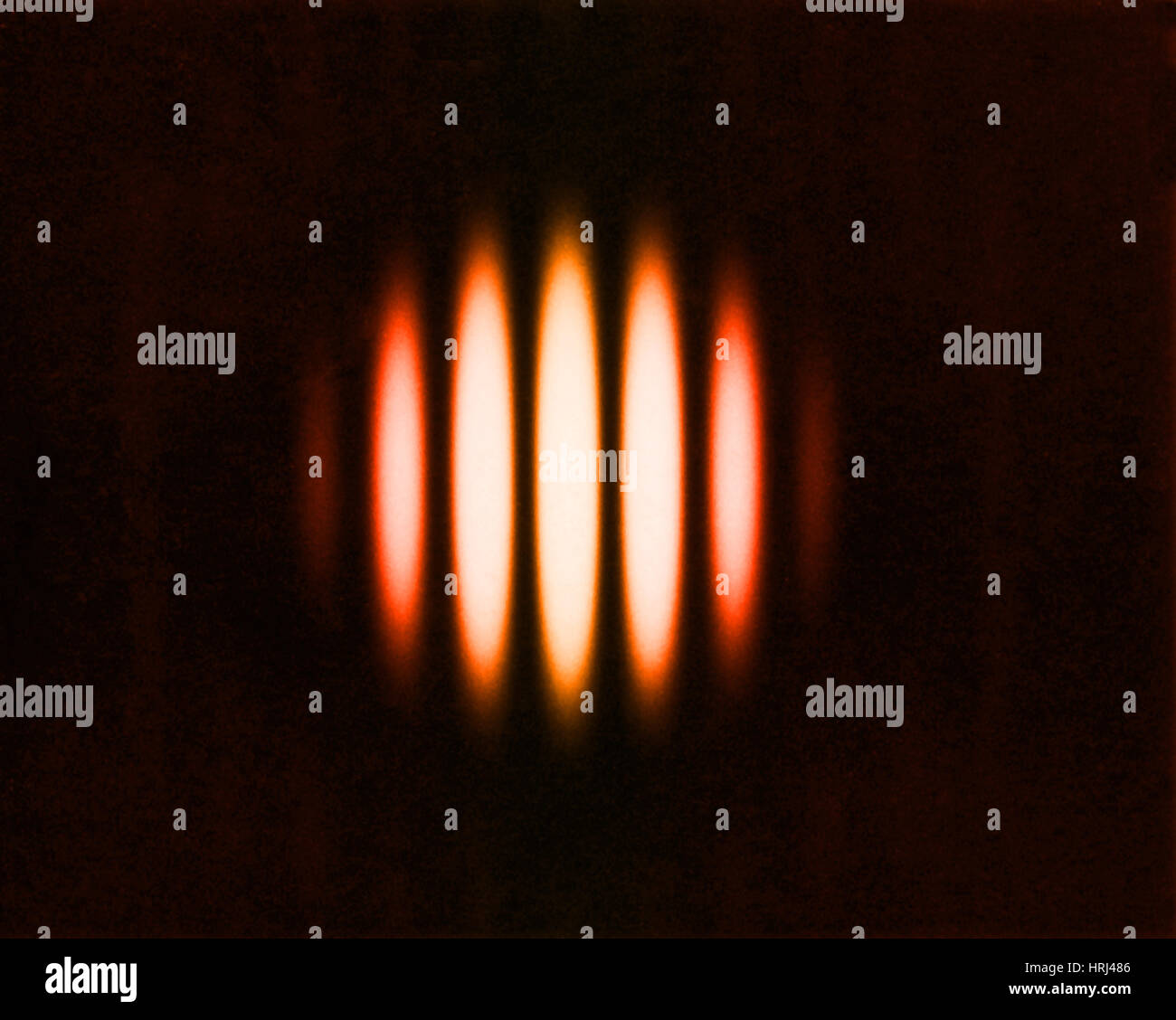
Young's double slit diffraction pattern using a white light source

A) The diffraction patterns (λ=1µm) along the orthogonal θxor

Schematic representation of the diffraction patterns on a plane

Electron diffraction patterns from rotational series of thin 3D ExbBD

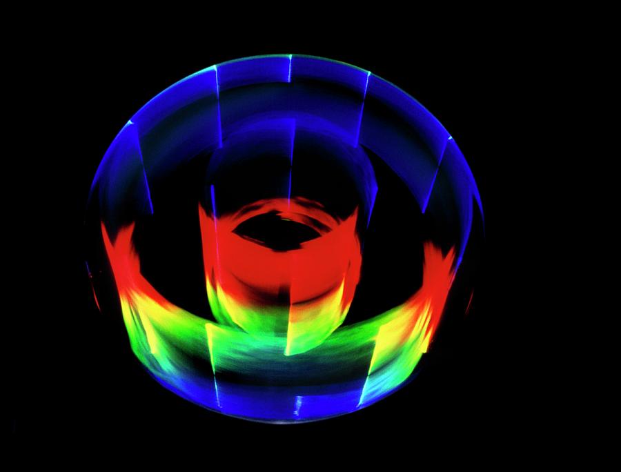
Circular Diffraction Pattern Photograph by James Stevenson/science

STEMinSEM electron diffraction patterns

Diffraction pattern double slit hires stock photography and images Alamy

Diffraction pattern Stock Image T205/0018 Science Photo Library

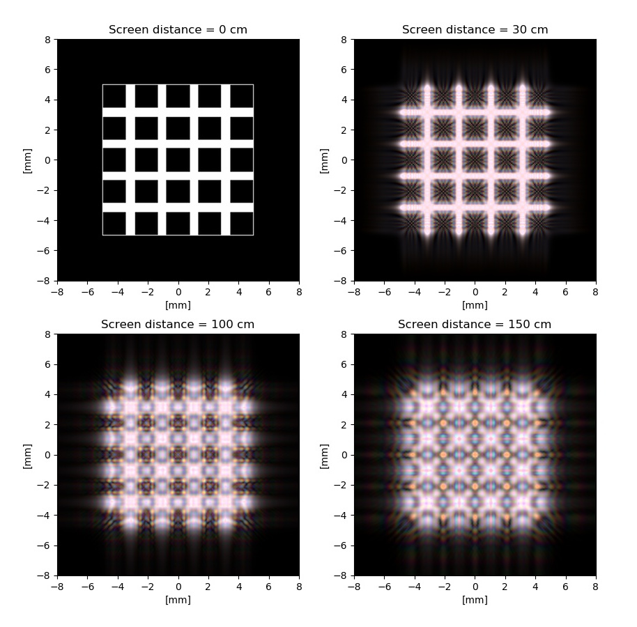
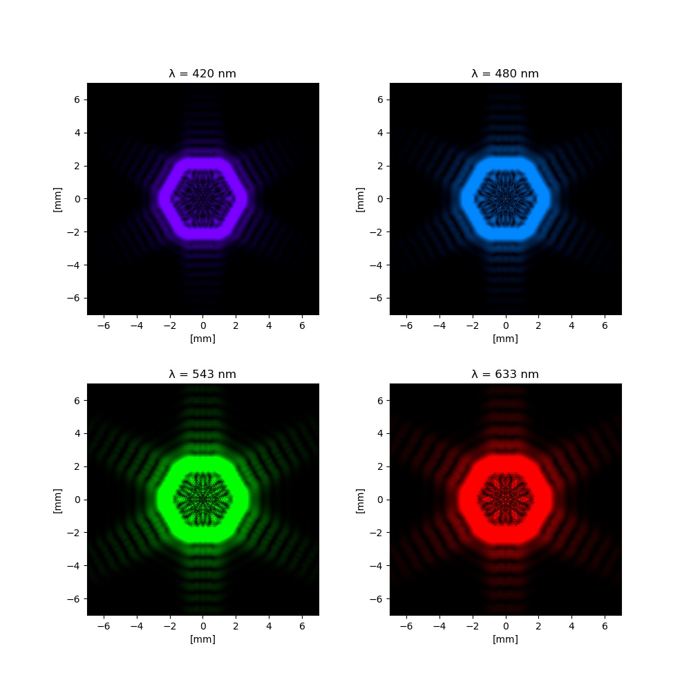
Simulating Diffraction Patterns with the Angular Spectrum Method and

Simulating Diffraction Patterns with the Angular Spectrum Method and
What Happens When There's Way More Than Two Holes?
A Diffraction Pattern Of A Red Laser Beam Projected Onto A Plate After Passing Through A Small Circular Aperture In Another Plate.
Web Tailoring Electron Vortex Beams With Customizable Intensity Patterns By Electron Diffraction Holography.
Note That The Central Maximum Is Larger Than Those On Either Side, And That The Intensity Decreases Rapidly On Either Side.
Related Post: